Cooling method and cooling system for electronic device

a cooling system and electronic device technology, applied in the field of cooling methods and cooling systems for electronic devices, can solve the problems of system halt, increased head generation of electronic devices, and increased running costs of air-conditioning equipment, so as to prevent dew condensation, reduce the electric power cost of air-conditioning systems, and maintain the effect of natural circulation

Inactive Publication Date: 2011-11-10
HITACHI PLANT TECH LTD
View PDF0 Cites 36 Cited by
  • Summary
  • Abstract
  • Description
  • Claims
  • Application Information

AI Technical Summary

Benefits of technology

[0074]According to this configuration, when the temperature of the outside air is equal to or lower than 10° C., it is possible to utilize “free cooling” in which a so-called chiller is not used and the cold water can be cooled by using only the outside air, and hence electric power costs for an air-conditioning system can be further reduced.
[0075]As described above, according to the cooling method and the cooling system for the electronic device of the present invention, it is possible to stably maintain the natural circulation of the refrigerant and to prevent dew condensation from being caused on the surface of the evaporator, even when the flow rate of the refrigerant of the evaporator is valve-controlled in the cooling system having the refrigerant natural circulation system.

Problems solved by technology

These electronic devices require a given temperature environment for a normal operation thereof, and if a high temperature state occurs, a trouble such as a system halt may be caused.
However, in recent years, along with a rapid increase in processing speed and processing ability of the electronic devices, an amount of head generated from the electronic devices steadily continues to increase, and the running cost of the air-conditioning equipment is also significantly increasing.
In addition, a method of cooling a server room by floor blow-out air conditioning using package air-conditioning equipment has been also adopted, but in order to suppress a local increase in temperature due to exhaust heat from the electronic device, it is necessary to air-condition the entire server room, which thus leads to a problem that the cooling efficiency is low.
Therefore, the refrigerant natural circulation system in which an operation state of the cooling system is significantly affected by the pipe resistance has a problem that the valve control may cause fluctuations in evaporation temperature.
For example, an evaporation pressure inside of the evaporator is decreased by the valve control, and accordingly a decrease in evaporation temperature more than necessary is caused, so that a considerable decrease in temperature at an exit of the evaporator may occur.
There is fear that this considerable decrease in temperature at the exit of the evaporator causes dew condensation on a surface of the evaporator.
If dew condensation is caused on the surface of the evaporator, there arise not only a problem that dew condensation water adversely affects the electronic device and accordingly the reliability is deteriorated but also a problem that an energy loss for preventing dew condensation occurs.
Accordingly, if the evaporation temperature fluctuates, the evaporation pressure also fluctuates, which thus leads to a problem that the natural circulation of the refrigerant becomes unstable.

Method used


Image

  • Cooling method and cooling system for electronic device
  • Cooling method and cooling system for electronic device
  • Cooling method and cooling system for electronic device

Examples


first embodiment

of the Present Invention

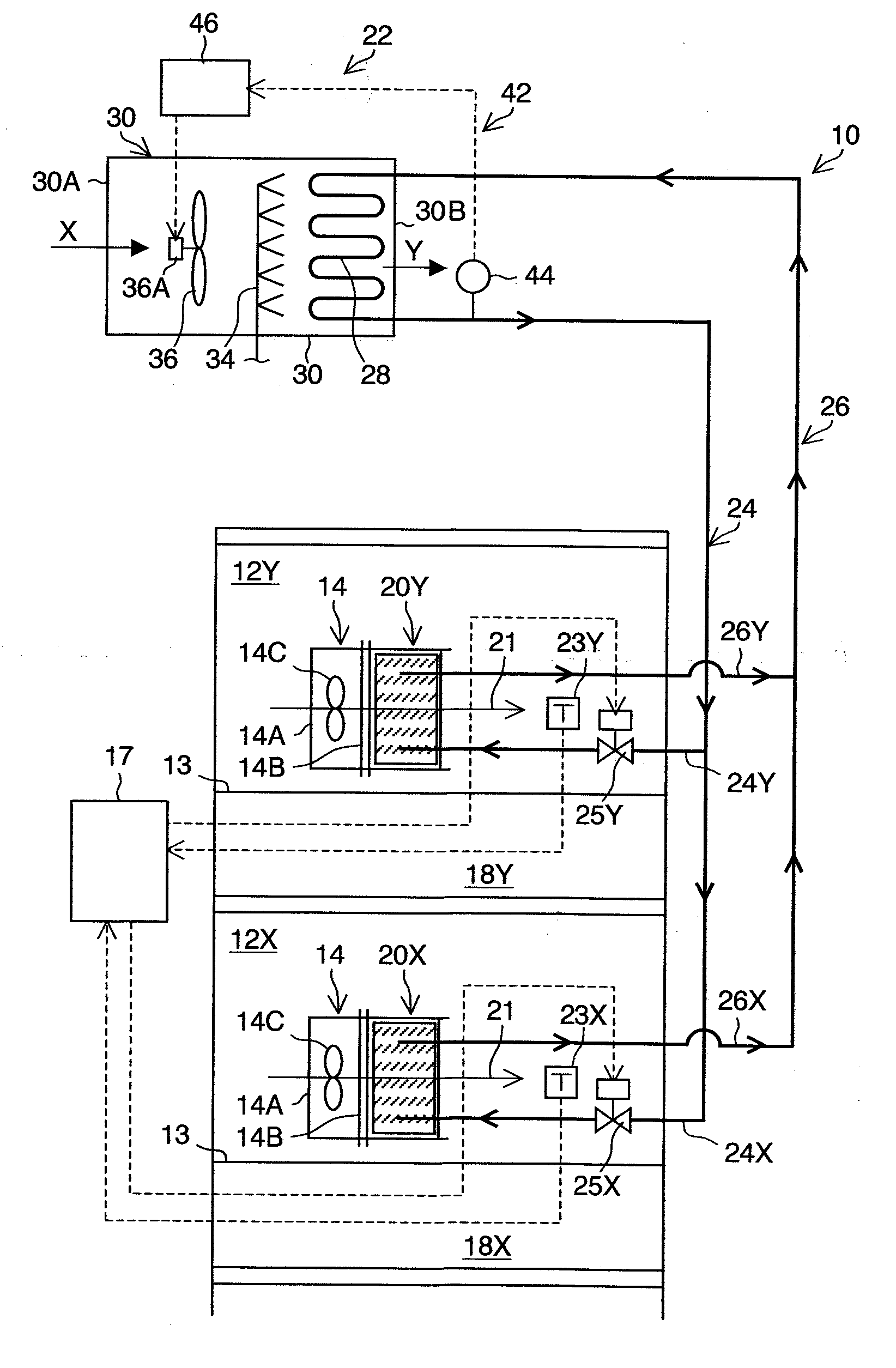
[0082]FIG. 1 is a conceptual diagram illustrating an overall configuration of a first embodiment of a cooling system 10 for an electronic device.

[0083]The cooling system 10 illustrated in FIG. 1 is a system which locally cools the vicinity of a server 14 provided in each of server rooms 12X and 12Y on lower and upper two floors. It should be noted that X attached to reference numeral in the following description designates a member relating to a cooling system on the lower floor, and Y attached to reference numeral in the following description designates a member relating to a cooling system on the upper floor. In addition, in FIG. 1, although one server 14 is illustrated in each of the server rooms 12X and 12Y, in reality, a large number of the servers 14 are placed therein. Further, normally, the servers 14 are stacked on top of one another to be housed in a server rack (not shown), and thus are installed in the server rooms 12X and 12Y.

[0084]The server 14 ...

second embodiment

of the Present Invention

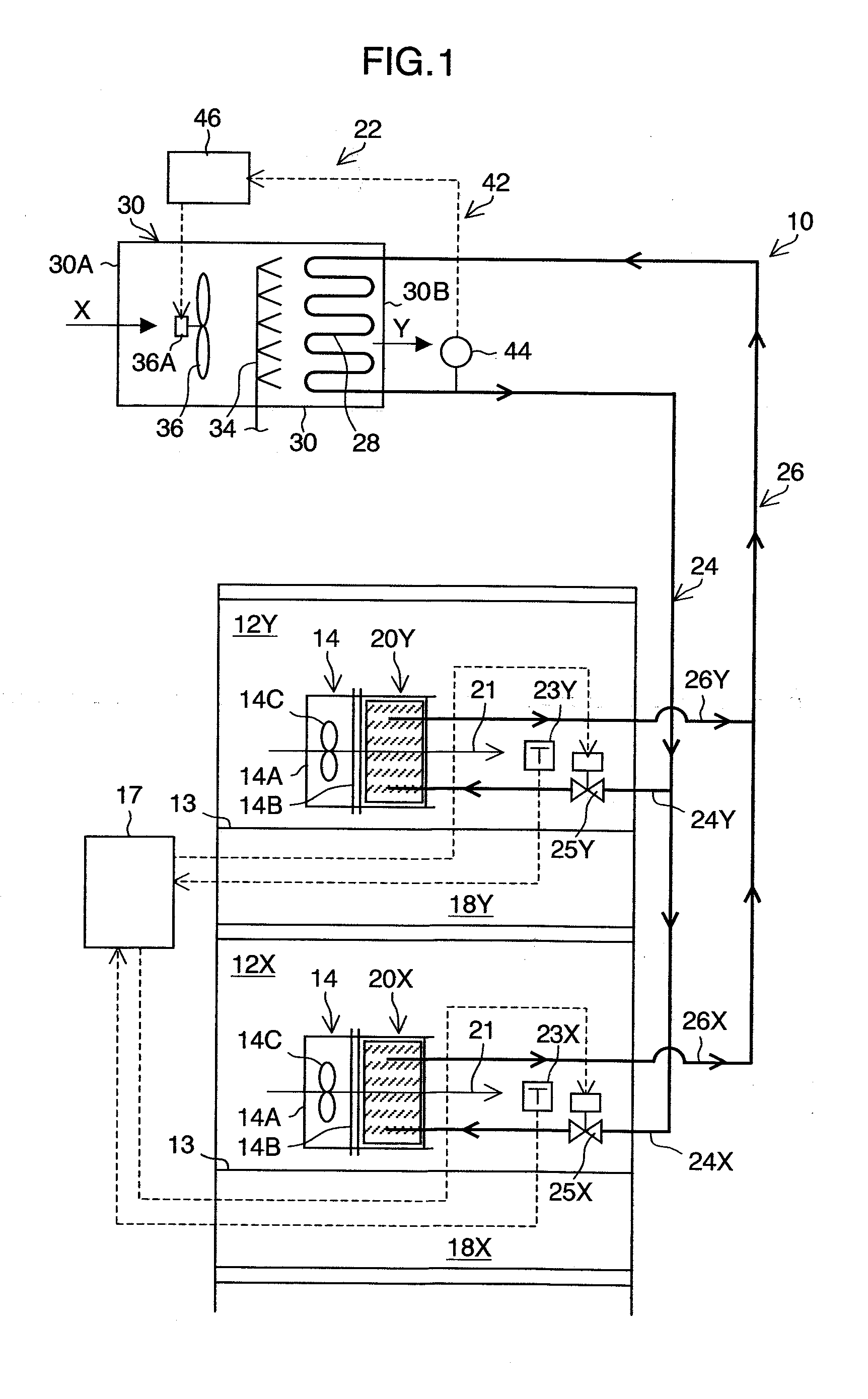
[0110]FIG. 2 is a conceptual diagram illustrating an overall configuration of a second embodiment of the cooling system 10 for the electronic device, and illustrates the case where a circulation duct type cooling tower is provided as the apparatus which condenses the refrigerant gas.

[0111]It should be noted that elements common to those of the first embodiment are denoted by the same reference symbols, and description thereof is omitted.

[0112]As illustrated in FIG. 2 and FIG. 3, a coupling hole 30C is opened on a side surface of the cooling tower main body 30 on the take-in port 30A side, and part of the exhaust port 30B and the coupling hole 30C are coupled to each other by a circulation duct 38. With this configuration, part of the exhaust outside air Y which has an increased temperature and is exhausted from the exhaust port 30B passes through the circulation duct38 to be circulated to the vicinity of the take-in port 30A, and hence the exhaust outside air...

third embodiment

of the Present Invention

[0124]FIG. 4 is a conceptual diagram illustrating an overall configuration of a third embodiment of the cooling system 10 for the electronic device, and illustrates the case where the cooling tower 22 according to each of the first and second embodiments is replaced with a cold water type condenser 48 as the apparatus which condenses the refrigerant gas.

[0125]It should be noted that elements common to those of the first and second embodiments are denoted by the same reference symbols, and description thereof is omitted.

[0126]As illustrated in FIG. 4, the heat exchange coil 28 coupled to the gas piping 26 and the liquid piping 24 and a cold water supply coil 50 coupled to a cold water supply apparatus (not shown) are provided inside of a cold water type condenser main body 49 (casing). Then, the refrigerant gas flowing through the heat exchange coil 28 and cold water flowing through the cold water supply coil 50 exchange heat with each other, so that the refri...


PUM


Abstract

A cooling method for an electronic device, comprising:
    • naturally circulating a refrigerant between: an evaporator which vaporizes the refrigerant by heat exchange with exhaust hot air from the electronic device, and cools the exhaust hot air; and one of a cooling tower and a condenser which is placed at a position higher than the evaporator, and liquefies the vaporized refrigerant; and
    • valve-controlling a flow rate of a refrigerant liquid to be supplied to the evaporator so that an air temperature after heat has been exchanged for cooling by the evaporator becomes a temperature suited to an operating environment of the electronic device, wherein
    • one of a condensation temperature and a condensation pressure of a refrigerant gas in one of the cooling tower and the condenser do not fluctuate even when the flow rate of the refrigerant liquid to be supplied to the evaporator is valve-controlled.

Description

BACKGROUND OF THE INVENTION[0001]1. Field of the Invention[0002]The present invention relates to a cooling method and a cooling system for an electronic device, and more particularly, to a cooling method and a cooling system for an electronic device which are used for locally cooling electronic devices such as a computer and a server placed in a server room by naturally circulating a refrigerant between an evaporator and a cooling tower (or a condenser).[0003]2. Description of the Related Art[0004]In a server room, a large number of electronic devices such as a computer and a server are installed in an intensive state. The electronic devices are installed generally in a rack mount system, that is, in a system in which the electronic devices are divided on a functional unit basis to be housed in a rack (casing) and such racks are stacked on top of one another in a cabinet. Then, a large number of such cabinets are arranged in a line on a floor of the server room.[0005]These electroni...

Claims


Application Information

Patent Timeline
Patent Type & Authority Applications(United States)
IPC IPC(8): F25D31/00F25B49/00F25D17/06F24F11/76
CPCG06F1/206G06F2200/201F25B23/006H05K7/20836H05K7/20809F24F11/76F24F2110/00F24F11/30F24F3/065G06F1/20H05K7/20709
Inventor KASHIRAJIMA, YASUHIROITO, JUNICHIINADOMI, YASUHIKOSENDA, MASAKATSUSHIMOKAWA, RYOJIOSHIMA, NOBORUSUGIURA, TAKUMI
Owner HITACHI PLANT TECH LTD
Why Eureka
Try Eureka