Water treatment system using alkaline water electrolysis device and alkaline fuel cell

a technology of water treatment system and fuel cell, which is applied in the direction of cell components, electrochemical generators, electrode coatings, etc., can solve the problems of inability to effectively separate tritium in the method, difficulty in conventional electrolytic concentration methods, and inability to use methods that are not practical, so as to achieve the effect of reducing the cost of electric power used for electrolysis, reducing the cost of water treatment, and efficient us

Active Publication Date: 2020-04-14
DE NORA PERMELEC LTD
View PDF23 Cites 0 Cited by
  • Summary
  • Abstract
  • Description
  • Claims
  • Application Information

AI Technical Summary

Benefits of technology

[0053](1) In the water treatment system using an alkaline water electrolytic device and an alkaline fuel cell according to the present invention, an alkaline water electrolytic device and an alkaline fuel cell are combined, and alkaline electrolysis is performed by utilizing electric power generated by the alkaline fuel cell using as raw materials a hydrogen gas and an oxygen gas which are generated by electrolysis in the alkaline water electrolytic device itself as electric power required in the alkaline water electrolytic device. Thus, after the start of electrolysis, alkaline water electrolysis can be continued using electric power generated in the system as electric power for alkaline water electrolysis, and electrolysis can be performed while electric power is regenerated, so that electric power costs required for water treatment can be considerably reduced.
[0054](2) In the water treatment system using an alkaline water electrolytic device and an alkaline fuel cell according to the present invention, a hydrogen gas and an oxygen gas generated by electrolysis in the alkaline water electrolytic device are used as a hydrogen gas and an oxygen gas as raw materials for the alkaline fuel cell. Therefore, it is unnecessary to supply the hydrogen gas and oxygen gas from the outside, and electric energy to be used as an electric power source for alkaline water electrolysis can be circulated and used in the system, so that energy can be efficiently used.
[0055](3) In the water treatment system using an alkaline water electrolytic device and an alkaline fuel cell according to the present invention, a hydrogen gas and an oxygen gas generated by electrolysis in the alkaline water electrolytic device may be used as a hydrogen gas and an oxygen gas as raw materials for the alkaline fuel cell. Thus, it is unnecessary to supply the hydrogen gas and oxygen gas from the outside, so that costs of electric power used for electrolysis can be considerably reduced.
[0056](4) In the water treatment system using an alkaline water electrolytic device and an alkaline fuel cell according to the present invention, a hydrogen gas and an oxygen gas generated by electrolysis in the alkaline water electrolytic device may be used as a hydrogen gas and an oxygen gas as raw materials for the alkaline fuel cell. Therefore, pure oxygen and hydrogen free from impurities such as a carbonaceous substance and a carbon dioxide gas can be used as raw materials, so that the alkaline fuel cell can be efficiently operated.
[0057](5) In the water treatment system using an alkaline water electrolytic device and an alkaline fuel cell according to the present invention, as raw materials for the alkaline fuel cell, not only the hydrogen gas and oxygen gas can be used, but also an electrolytic solution that is used for electrolysis in the alkaline water electrolytic device can be used as the electrolytic solution formed of an alkaline aqueous solution. Thus, for all the raw materials for the alkaline fuel cell, all the materials that are used or generated by the alkaline water electrolytic device can be circulated and used.
[0058](6) In the water treatment system using an alkaline water electrolytic device and an alkaline fuel cell according to the present invention, electric power to be used for electrolysis in the alkaline water electrolytic device is partially fed from the alkaline fuel cell after the start of electrolysis. Water generated by the alkaline fuel cell is used as supplementary water for water lost through electrolysis in the alkaline electrolytic device. Thus, all the raw materials for the alkaline water electrolytic device can be supplied by electric power and water that are generated by the alkaline fuel cell.

Problems solved by technology

However, remained only at an experimental level, and such a method has not been put into practical use yet.
However, efficient separation of tritium is difficult in the methods except for the water electrolytic method.
In practice, however, conventional electrolytic concentration methods have some problems.
These problems include the following: experimental operations are complicated; the tritium concentration ratio is limited by the upper limit of the electrolyte concentration; a mixed gas of hydrogen and oxygen may be generated to cause explosion; much time is required for electrolysis; and electric power consumption becomes enormous, so that it is difficult to treat a large volume of water.
However, the method described in Patent Literature 1 has the disadvantage that electric power consumption becomes enormous as described above, and this disadvantage is the biggest obstacle to employment of an electrolytic method.
However, the proton conductive fuel cell has the problem of a high cost and small resource amount associated with noble metals because the fuel cell operates under a strong acid atmosphere, and therefore the catalyst to be used is almost limited to a platinum-based noble metal.
Since the electrolyte is an aqueous solution, the operation temperature range is limited to temperatures at which the electrolytic solution is not frozen and evaporated.
Since the mobility (diffusion coefficient) of ions varies depending on the temperature, so that electric power generation is affected, the temperature condition is severe.
The use of reformed hydrogen containing the above-described substances as impurities is not desired, and as oxygen and hydrogen, pure oxygen and hydrogen raw materials which do not contain CO2 are required.
Meanwhile, in the alkaline water electrolytic device, a large amount of electric energy is required, and therefore if all the electric energy must be supplied from the outside, enormous costs are necessary.

Method used


Image

  • Water treatment system using alkaline water electrolysis device and alkaline fuel cell
  • Water treatment system using alkaline water electrolysis device and alkaline fuel cell
  • Water treatment system using alkaline water electrolysis device and alkaline fuel cell

Examples


example 1

[0135]A simulated liquid of raw water containing tritiated water that does not contain impurities (hereinafter, also referred to as a “simulated liquid”), a simulated liquid with the following components was used.

[0136]Simulated Liquid: 180 L

[0137]Initial concentration of tritium in simulated liquid: 4.2×10⁶ Bq / L

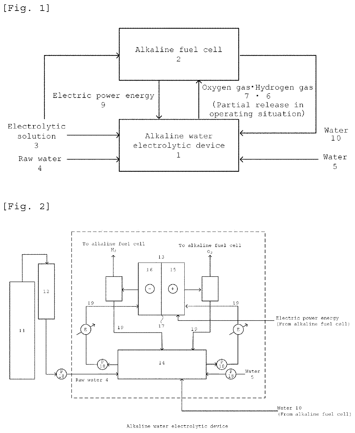
[0138]As illustrated in FIG. 2, a raw water storage tank 11 containing 180 L of the simulated liquid was provided. In this test, the simulated liquid was fed from the raw material storage tank 11 to a circulation tank 14 through a treatment bath 12. Specifically, 9.67 L / day of the simulated liquid was fed from the raw material storage tank 11 to the circulation tank 14 through the treatment bath 12 by a pump 18. In this test, the simulated liquid was continuously fed in an alkaline water electrolytic device.

[0139]To the circulation tank 14, 9.60 L / day of the simulated liquid is fed by the pump 18, and also alkaline aqueous solution is fed. In the circulation tank 14, the sim...

example 2

[0164]Except that the raw water used in Example 1 was replaced by pure water, just the same procedure as in Example 1 was carried out to obtain the same results as in Example 1.

example 3

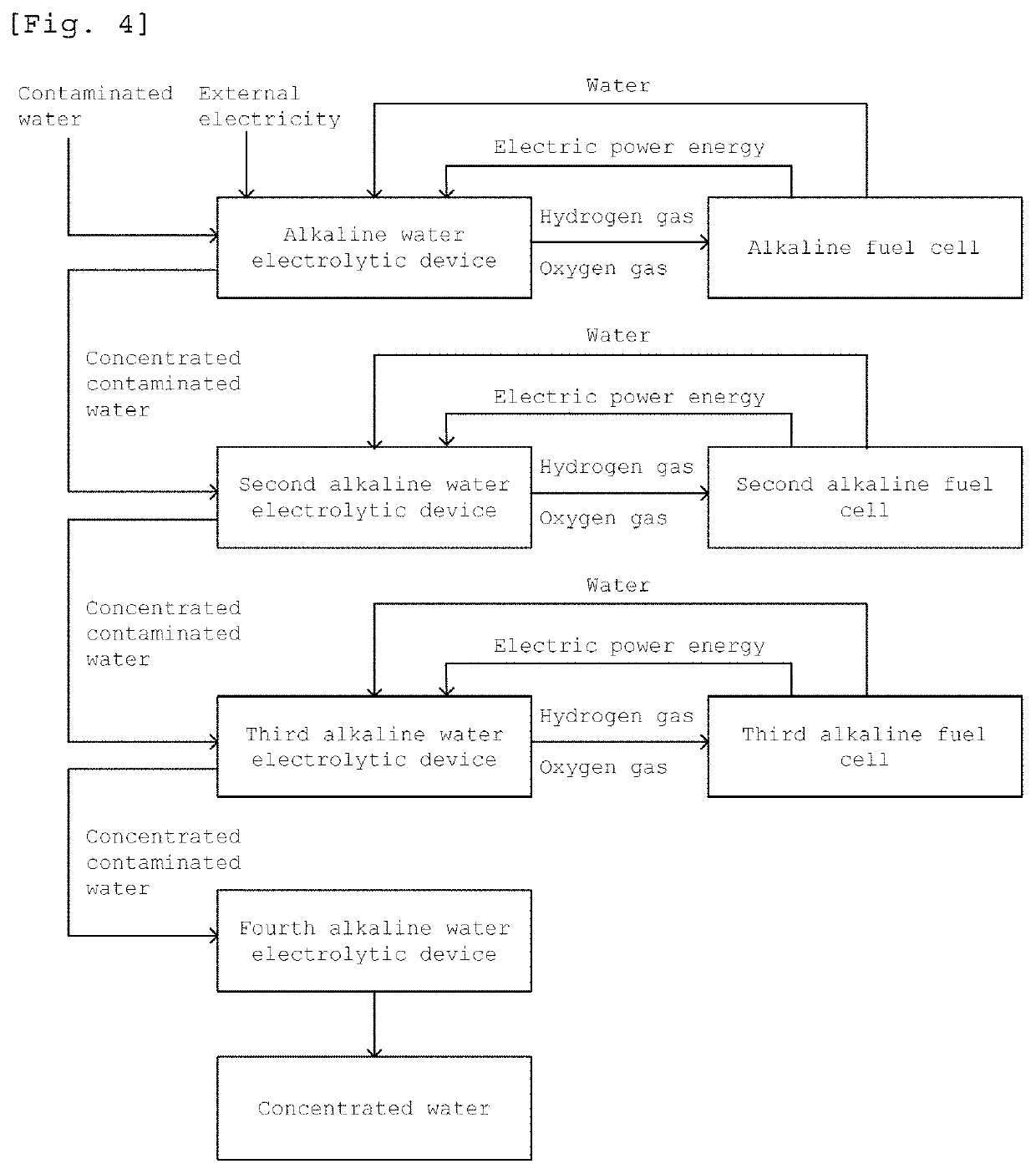
[0165]As illustrated in FIG. 4, 2nd, 3rd and 4th alkaline water electrolytic devices and 2nd and 3rd alkaline fuel cells were connected to the alkaline water electrolytic device 1 and the alkaline fuel cell 2 in a cascade mode, respectively.

[0166]180 L of the simulated water used in Example 1 is used as raw water (contaminated water), and the electrolytic solution (alkali concentration of 20% by mass) formed of the contaminated water and the alkaline aqueous solution is used. First, the alkaline water electrolytic device is started by external electric power, and the hydrogen gas and oxygen gas obtained by the alkaline electrolysis are sent to the alkaline fuel cell. Electric energy and water are collected by the alkaline fuel cell. Electrolysis is continued using the obtained electric energy, the obtained water is used as supplementary water for the alkaline water electrolytic device, alkaline water electrolysis is continued, and the contaminated water is concentrated. The concentr...


PUM

PropertyMeasurementUnit
mass %aaaaaaaaaa
temperatureaaaaaaaaaa
current densityaaaaaaaaaa

Abstract

Provided is a water treatment system using an alkaline water electrolytic device and an alkaline fuel cell in which for continuing an electrolytic treatment, a hydrogen gas and an oxygen gas required in an alkaline water electrolytic device and an alkaline fuel cell, an amount of water corresponding to raw water lost through the electrolytic treatment, and an electrolytic solution are efficiently circulated and used in a water treatment system to considerably reduce electric power consumption. The water treatment system is a water treatment system using an alkaline water electrolytic device and an alkaline fuel cell in which an alkaline water electrolytic device and an alkaline fuel cell are connected to each other, the volume of raw water is reduced, an oxygen gas and a hydrogen gas that are generated from the alkaline water electrolytic device are fed to the alkaline fuel cell, the oxygen gas and hydrogen gas are used to generate electric power by the alkaline fuel cell, electric energy and water are collected, and the collected electric energy is fed to the alkaline water electrolytic device as an electric power source thereof.

Description

TECHNICAL FIELD[0001]The present invention relates to a water treatment system using an alkaline water electrolytic device and an alkaline fuel cell in which an alkaline water electrolytic device and an alkaline fuel cell each having an alkaline aqueous solution as an electrolytic solution are combined, hydrogen and oxygen generated by the alkaline water electrolytic device are used as raw materials for the alkaline fuel cell to generate electric power, and an electrolytic treatment is performed by the alkaline water electrolytic device using the resulting electric energy and water.[0002]The present invention also relates to a water treatment system using an alkaline water electrolytic device and an alkaline fuel cell in which to an alkaline water electrolytic device and an alkaline fuel cell, 2nd, 3rd, . . . and nth alkaline water electrolytic devices and 2nd, 3rd, . . . and nth alkaline fuel cells are connected in a cascade mode, electrolysis is performed continuously, and the vol...

Claims


Application Information

Patent Timeline
Patent Type & Authority Patents(United States)
IPC IPC(8): H01M8/00C25B15/02H01M8/0662H01M4/90C02F1/461C25B9/10G21F9/06C25B1/10C25B11/04C25B15/08H01M8/0656H01M8/18H01M8/083H01M4/92C25B9/23
CPCC25B15/02C25B11/0473H01M8/0681H01M4/9016C25B11/0494C25B11/0447C02F1/46114G21F9/06C25B15/08H01M8/186C25B9/10C25B1/10H01M8/0656H01M4/9041Y02E60/366H01M4/926Y02E60/528C02F2001/46133H01M8/083Y02E60/36Y02E60/50C25B1/04C25B9/73C25B9/23C25B11/075C25B11/081C25B11/097H01M8/0606H01M8/10C25B11/043
Inventor MANABE, AKIYOSHITSUJII, FUMIYAKATO, AKIHIRO
Owner DE NORA PERMELEC LTD
Why Eureka
Try Eureka