Plasma processing apparatus

a processing apparatus and plasma technology, applied in the direction of chemical apparatus and processes, coatings, chemical vapor deposition coatings, etc., can solve the problems of fluctuation of electron temperature, plasma density between discharge units, etc., and achieve the effect of increasing the cost per unit electric power

Inactive Publication Date: 2013-04-25
HITACHI LTD
View PDF9 Cites 2 Cited by
  • Summary
  • Abstract
  • Description
  • Claims
  • Application Information

AI Technical Summary

Benefits of technology

[0010]According to an aspect of the present invention, it is possible to provide a plasma processing apparatus that can generate uniform plasma without increasing costs per unit electric power even in the case where the discharge area is increased to adapt to samples (bodies to be processed) in given sizes by arranging a plurality of plasma discharge units.

Problems solved by technology

On the other hand, it has been found that such problems arise when using a plurality of power supplies in that it is likely to cause faulty discharge due to phase differences between the power supplies and it is likely to cause fluctuations in the plasma density between the discharge units and fluctuations in electron temperature.

Method used


Image

  • Plasma processing apparatus
  • Plasma processing apparatus
  • Plasma processing apparatus

Examples


first embodiment

[0037]A first embodiment will be described with reference to FIGS. 1 to 9.

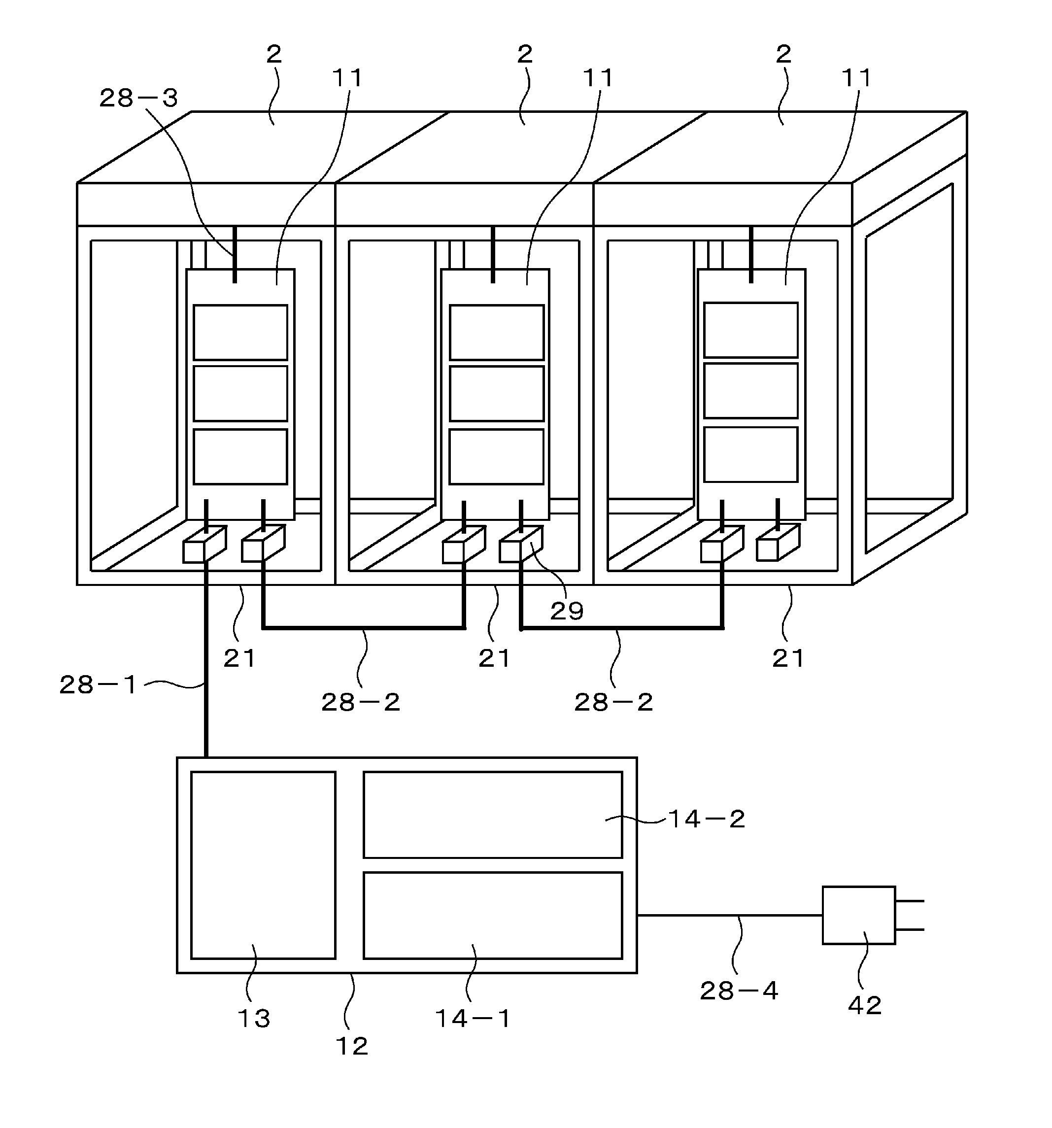
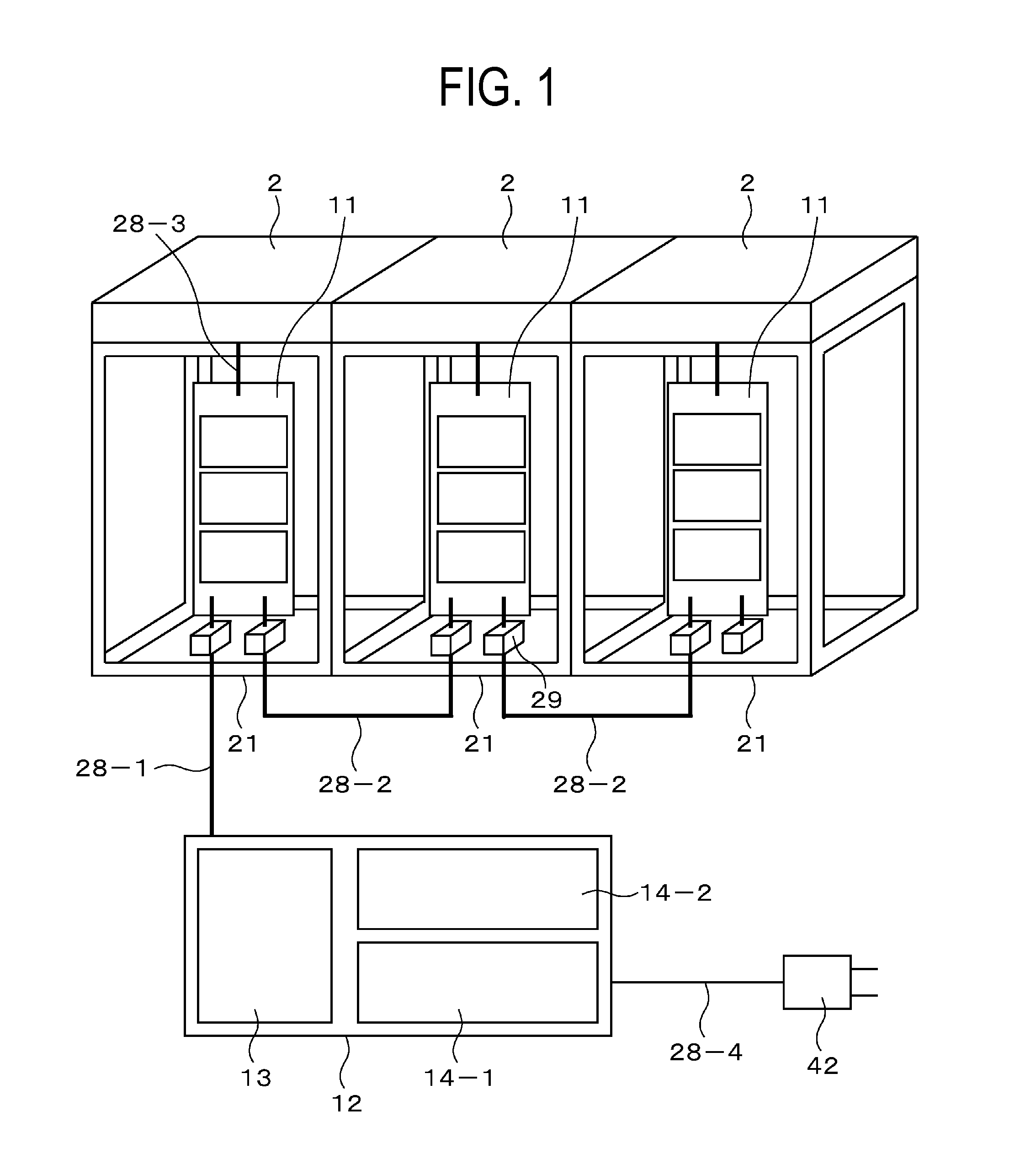
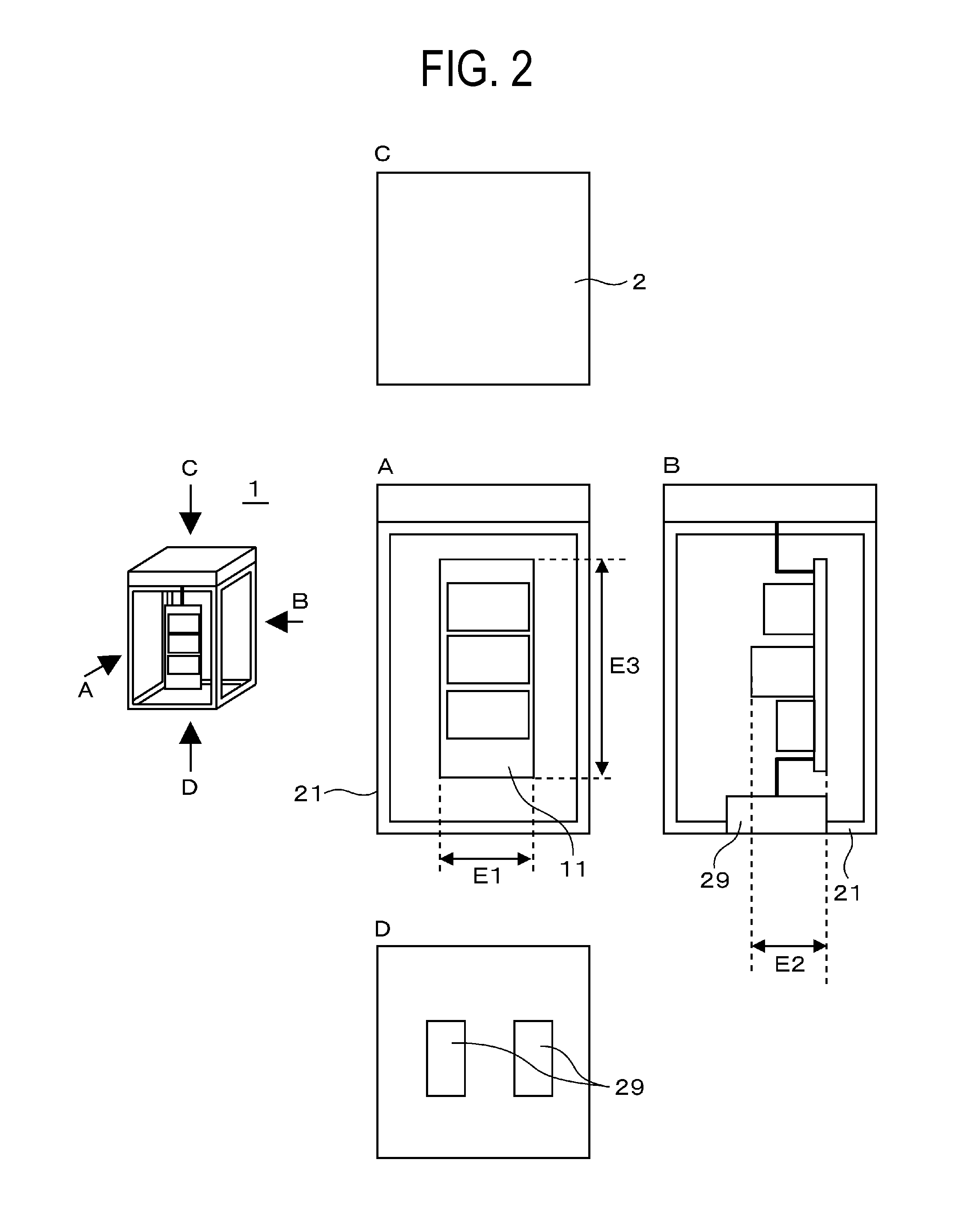
[0038]FIG. 1 is a schematic block diagram of the main part of a plasma processing apparatus according to the embodiment, showing the configuration of a plasma module array. In the embodiment, three plasma modules are arranged in the lateral direction. FIG. 2 is a diagram of the configuration of a single plasma module in more detail. FIG. 3 is the outline of wiring connections between various circuits of the plasma processing apparatus including the plasma modules. FIG. 4 is a schematic diagram of the configuration of a control unit of the plasma processing apparatus.

[0039]As illustrated in FIG. 2, a plasma module 1 has the basic configuration of a case 21, an RF power circuit 11 accommodated in the case, and a discharge electrode 2 mounted on the upper part of the case 21. It is noted that a reference numeral 29 denotes a connector, and reference numerals E1, E2, and E3 denote the width, height, and length of ...

second embodiment

[0061]Next, a second embodiment of the present invention will be described with reference to FIGS. 10 to 16. It is noted that points described in the first embodiment but not described in the second embodiment are also applicable to the second embodiment unless otherwise specified.

[0062]FIG. 10 is a schematic block diagram of an overall plasma processing apparatus (a plasma film deposition apparatus) according to the embodiment. The plasma film deposition apparatus is a film deposition apparatus according to a method in which a substrate (a body) 6 to be processed is provided directly above a discharge electrode 2 and plasma 3 is generated above the substrate 6 to be processed for film deposition. This processing apparatus 31 is provided with a case (a processing chamber) 34 that forms a processing chamber, a plasma module 1, and a roller 32 that carries the body 6 to be processed. Moreover, a gas atmosphere switching unit 33 that switches a gas atmosphere between the inside of the ...

third embodiment

[0069]A third embodiment of the present invention will be described with reference to FIG. 17 to FIGS. 19A and 19B. It is noted that points described in the first or second embodiment but not described in the third embodiment are also applicable to the third embodiment unless otherwise specified.

[0070]FIG. 17 is a schematic block diagram of an overall ozone processing apparatus that is one of plasma processing apparatuses. FIGS. 18A to 18C are schematic block diagrams of a gas supply unit and a plasma discharge unit of the ozone processing apparatus. FIG. 18A is a top view, FIG. 18B is a side view seen from the X-direction in FIG. 18A, and FIG. 18C is a side view see from the Y-direction in FIG. 18A. FIGS. 19A and 19B are diagrams illustrative of simple examples of a gas blow method. FIG. 19A is an example of a desirable case, and FIG. 19B is an example of an undesirable case. In a plasma processing apparatus (an ozone processing apparatus) 31, a plurality of plasma modules 1 are pr...


PUM

PropertyMeasurementUnit
thickness T2aaaaaaaaaa

Abstract

There is provided a plasma processing apparatus that can generate uniform plasma without increasing costs per unit electric power even though the discharge area is increased to adapt to samples in given sizes by arranging a plurality of plasma discharge units. A plasma processing apparatus includes an RF power supply having an RF signal circuit and an RF power circuit, a case, and a discharge electrode. A plasma module is configured of the discharge electrode and the RF power circuit provided in the case. A frequency signal from the RF signal circuit is inputted to a plurality of the plasma modules connected in parallel with each other.

Description

CLAIM OF PRIORITY[0001]The present application claims priority from Japanese Patent Application JP 2011-230222 filed on Oct. 20, 2011, the content of which is hereby incorporated by reference into this application.BACKGROUND OF THE INVENTION[0002]1. Field of the Invention[0003]The present invention relates to a plasma processing apparatus for use in processing such as film deposition, surface modification, and cleaning using plasma.[0004]2. Description of the Related Art[0005]In recent years, with the advancement of studies on the techniques of generating plasma at an atmospheric pressure, methods that use plasma for forming a functional film such as DLC (Diamond-Like Carbon), for removing organic substances on material surfaces, for sterilization, or the like have been widely studied. For example, US Patent Application Publication No. US2007 / 0123041A1 describes a structure in which a plurality of discharge electrode plates are arranged in parallel with each other on a plasma proces...

Claims


Application Information

Patent Timeline
Patent Type & Authority Applications(United States)
IPC IPC(8): C23C16/509B08B13/00
CPCH01J37/32174H01J37/32366H01J37/32376B08B7/0035H01J37/32577H01J37/32899H01J2237/335H01J37/32541H01J37/32082H01J37/32155H01J37/32532
Inventor KOBAYASHI, HIROYUKINAGAISHI, HIDEYUKITANDOU, TAKUMIITABASHI, NAOSHI
Owner HITACHI LTD
Why Eureka
Try Eureka