Refrigerator
a technology of refrigerator and heat exchange efficiency, which is applied in the field of refrigerators, can solve the problems of affecting the heat exchange efficiency of the evaporator, increasing the flow resistance, and high power consumption, and achieves the reduction of power consumption, the reduction of the flow resistance of refrigerant, and the quick removal of frost on the entire surface of the evaporator.
- Summary
- Abstract
- Description
- Claims
- Application Information
AI Technical Summary
Benefits of technology
Problems solved by technology
Method used
Image

Examples
first embodiment
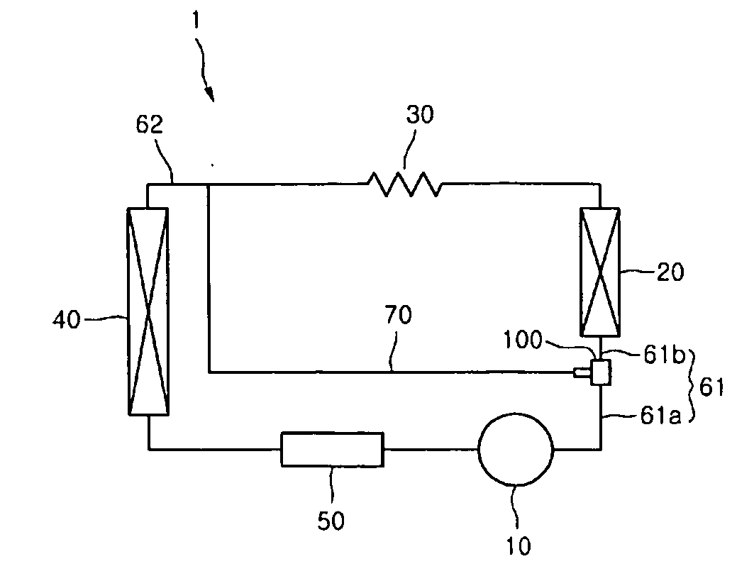
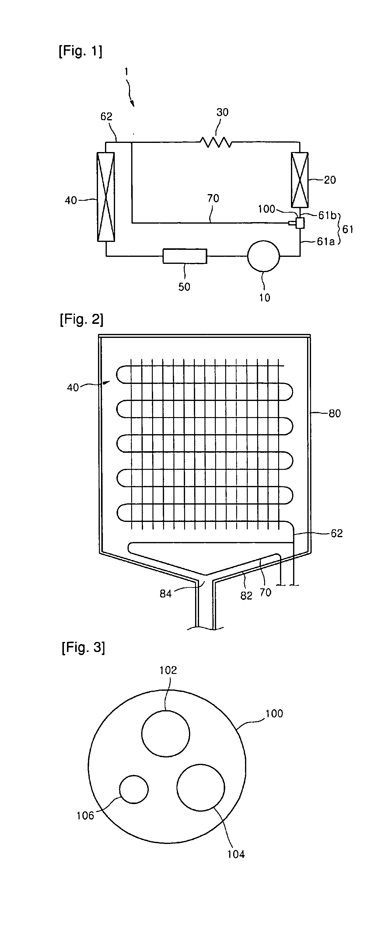
[0026]FIG. 1 is a schematic view of a refrigerant system of a refrigerator according to a
[0027]Referring to FIG. 1, a refrigerator 1 including a refrigerant system according to the first embodiment includes a compressor 10, a condenser 20, an expansion valve 30, an evaporator 40, and a vapor-liquid separator 50. The compressor 10 compresses refrigerant to high temperature and pressure, and the condenser 20 condenses the compressed refrigerant. The expansion valve 30 expands the condensed refrigerant. The evaporator 40 evaporates the refrigerant expanded through the expansion valve 30. The vapor-liquid separator 50 is disposed between the evaporator 40 and the compressor 10 to separate the liquid refrigerant and the vapor refrigerant having passed through the evaporator 40.
[0028]In detail, the compressor 10 is connected with the condenser 20 through a first connecting pipe 61. The expansion pipe 30 is connected with the evaporator 40 through a second connecting pipe 62.
[0029]The firs...
second embodiment
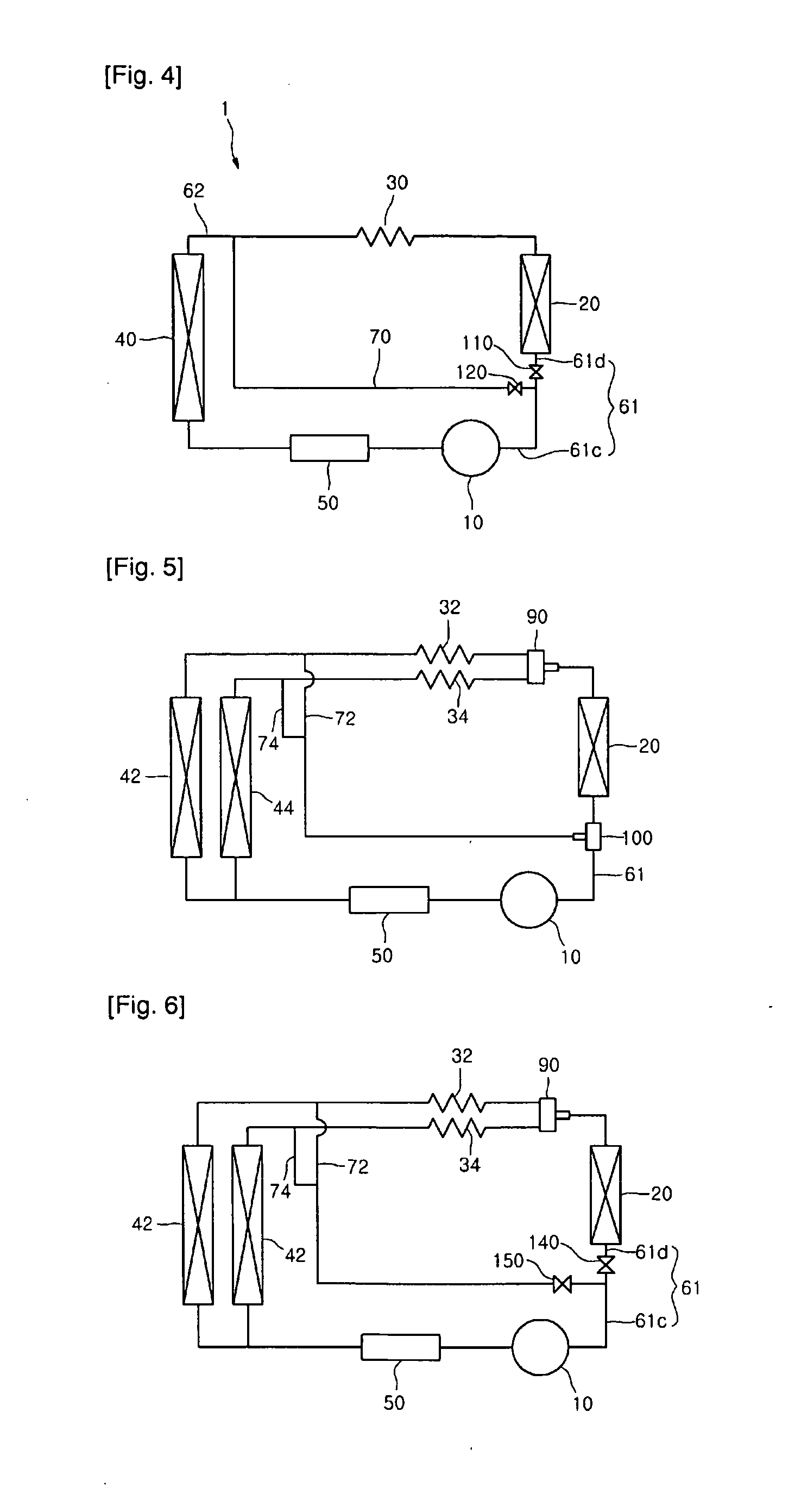
[0051]FIG. 4 is a schematic view of a refrigerant system according to a
[0052]Since the second embodiment is the same as the first embodiment except the structure of a valve device, detailed description will be omitted herein.
[0053]Referring to FIG. 4, a valve device according to the second embodiment includes a first valve 110 and a second valve 120. The first valve 110 is provided in a first connecting pipe 61 that connects the compressor 10 with the condenser 20. The second valve 120 is provided in the bypass pipe 70.
[0054]In detail, the bypass pipe 70 diverges from the first connecting pipe 61. The first connecting pipe 61 may be divided into a compressor discharge-side pipe 61c and a condenser intake-side pipe 61d by the bypass pipe 70. The first valve 110 is provided in the condenser intake-side pipe 61d.
[0055]The first valve 110 is opened and the second valve 120 is closed in a normal operation of the refrigerator. In this case, high-temperature refrigerant discharged from th...
third embodiment
[0057]FIG. 5 is a schematic view of a refrigerant system according to a
[0058]Referring to FIG. 5, the refrigerant system according to the third embodiment includes a compressor 10, a condenser 20, a plurality of evaporators, expansion valves of the same number as the evaporators, and a plurality of bypass pipes. The bypass pipes allow refrigerant discharged from the compressor 10 to flow into the evaporators.
[0059]In detail, the evaporators include an evaporator 42 for a freezing compartment and an evaporator 44 for a refrigeration compartment. The expansion valves include a first expansion valve 32 for expanding refrigerant to flow into the evaporator 42 a second expansion valve 34 for expanding refrigerant to flow into the evaporator 44.
[0060]The bypass pipes include a first bypass pipe 72 and a second bypass pipe 74. The first bypass pipe 72 allows high-temperature refrigerant discharged from the compressor 10 to move toward an inlet of the evaporator 42. The second bypass pipe 7...
PUM
 Abstract
Description
Claims
Application Information
 - R&D
- Intellectual Property
- Life Sciences
- Materials
- Tech Scout
- Unparalleled Data Quality
- Higher Quality Content
- 60% Fewer Hallucinations
Browse by: Latest US Patents, China's latest patents, Technical Efficacy Thesaurus, Application Domain, Technology Topic, Popular Technical Reports.
© 2025 PatSnap. All rights reserved.Legal|Privacy policy|Modern Slavery Act Transparency Statement|Sitemap|About US| Contact US: help@patsnap.com