
Device for supporting solar modules

a technology for solar modules and devices, applied in the direction of photovoltaic supports, heat collector mounting/supports, light and heating apparatus, etc., can solve the problems of high manufacturing cost, high labor intensity, and inability to manufacture standard profiles, so as to simplify and accelerate the assembly process, the effect of inexpensive materials and inexpensive manufacturing of devices

Inactive Publication Date: 2011-11-10
IDEEMATEC DEUTSCHLAND GMBH
View PDF13 Cites 27 Cited by
  • Summary
  • Abstract
  • Description
  • Claims
  • Application Information

AI Technical Summary

Benefits of technology

[0023]A particular advantage of the invention is that the configuration chosen for the head piece makes it possible to attach it both to the post and to the transverse beam using the same connecting elements, in particular bolt-nut-pairs of the same size, particularly preferably M12 bolts and corresponding nuts. Such material is inexpensive, and the use of only a single screw / bolt size simplifies and accelerates the assembly process.
[0024]Preferably, the transverse beam is also designed as a profiled element, in particular a Z, U or T profiled element. The head pieced is attached preferably to the bridge or middle part of the profile, which rests more or less vertically against the middle part of the head piece.
[0025]Preferably, the post, the head piece, the transverse beam and the strut are made as profiled elements. This allows for a particularly inexpensive manufacture of the device according to the invention.
[0026]According to a special embodiment, the head piece and the transverse beam are made with an identical profile, in particular a U profile.
[0027]These and other advantages of the invention will be further understood and appreciated by those skilled in the art by references to the following written specification, claims and appended drawings.

Problems solved by technology

In most solutions according to the prior art, said head piece is complexly designed, for example canted in various directions, which makes it expensive to manufacture and labor-intensive to mount.
Said transverse beam holders are very complexly designed since the transverse beam is fixed to the first transverse beam holder by means of a first supporting joint and to the second transverse beam holder by means of a second supporting joint.
Also this solution is complex and, thus, cost-intensive, due to the required joints.
Consequently, no head piece is required on the post, however, the transverse beams are designed accordingly complex and cannot be made from standard profiles.

Method used


Image

  • Device for supporting solar modules
  • Device for supporting solar modules
  • Device for supporting solar modules

Examples


Embodiment Construction

[0037]For purposes of description herein, the terms “upper,”“lower,”“right,”“left,”“rear,”“front,”“vertical,”“horizontal,” and derivatives thereof shall relate to the invention as oriented in FIG. 1. However, it is to be understood that the invention may assume various alternative orientations, except where expressly specified to the contrary. It is also to be understood that the specific devices and processes illustrated in the attached drawings, and described in the following specification are simply exemplary embodiments of the inventive concepts defined in the appended claims. Hence, specific dimensions and other characteristics relating to the embodiments disclosed herein are not to be considered as limiting, unless the claims expressly state otherwise.

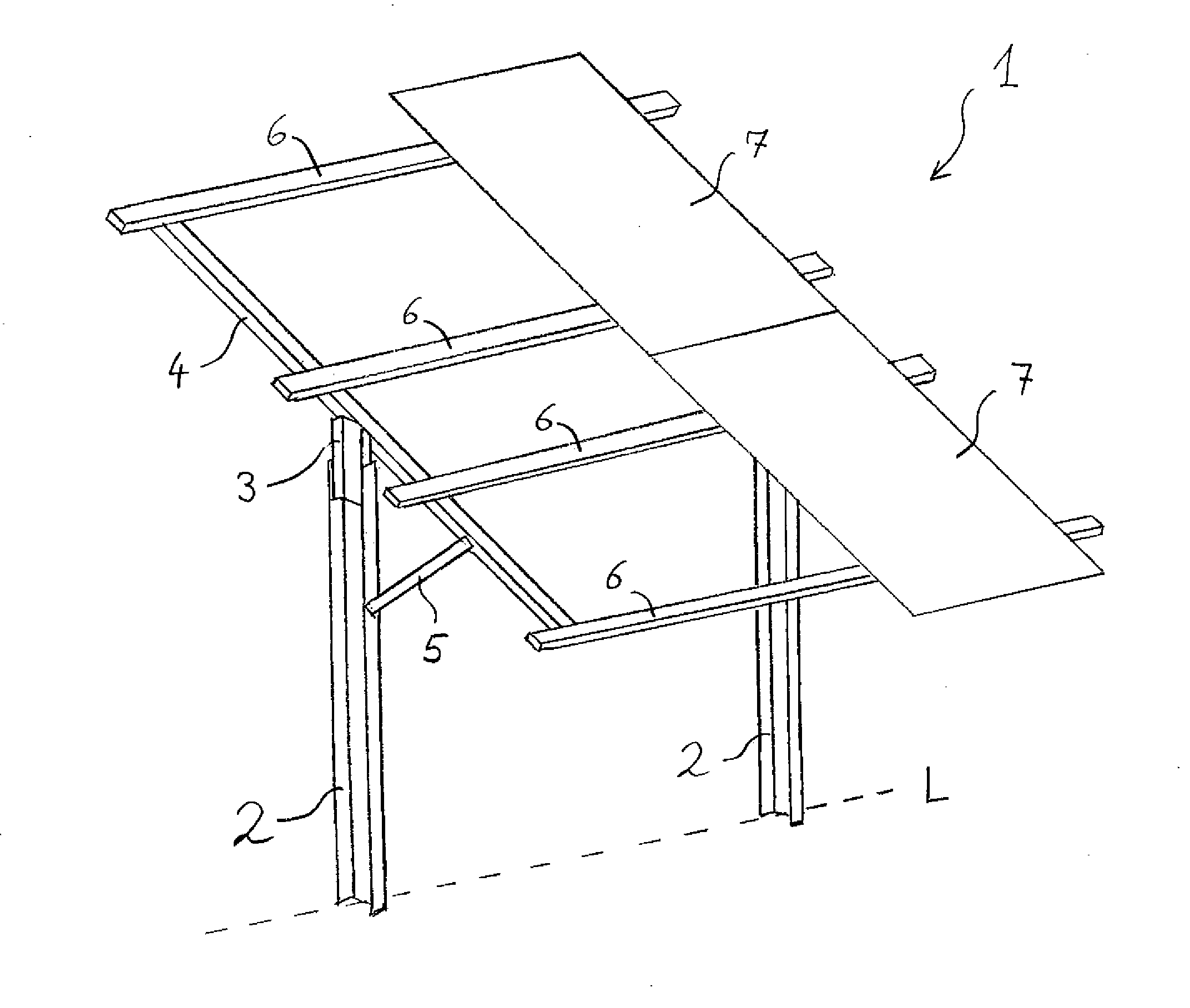
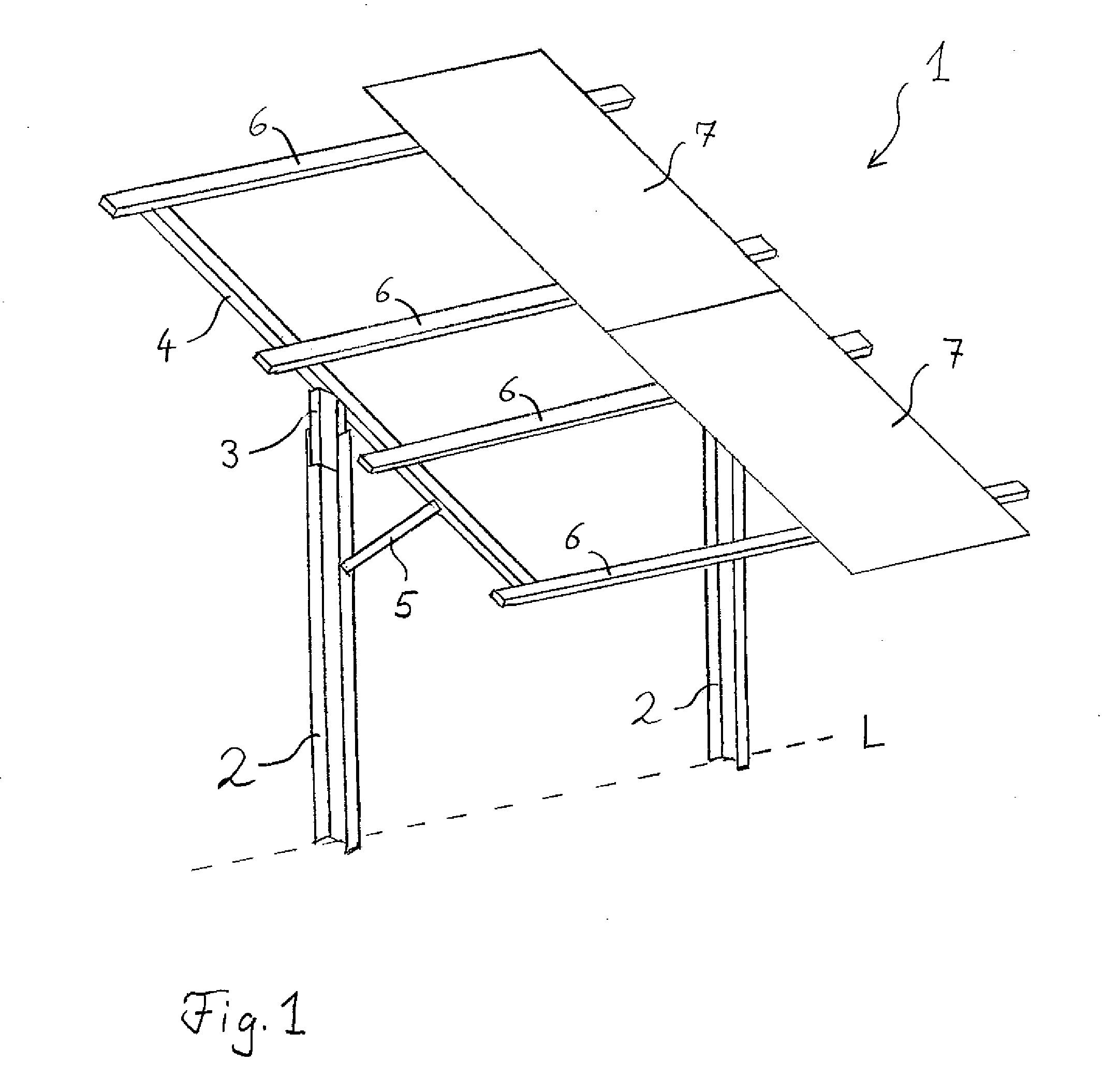
[0038]FIG. 1 shows the basic structure of a support according to the invention. Preferably, said support is a fixed support, i.e. the azimuth angle is not followed. Also the inclination of the transverse beams 4 relative to the h...


PUM


Abstract

A device for supporting solar modules, including several posts arranged in a row, wherein a head piece is attached to each post in its upper end region and at each head piece a transverse beam oriented more or less transversely to the row of posts is fixed, characterized in that the head piece is a profiled element, and that there is a strut between each transverse beam and the post, at the head piece of which the transverse beam is fixed.

Description

BACKGROUND OF THE INVENTION[0001]The invention relates to a device for supporting solar modules, comprising several posts in a row, wherein a head piece is attached to each post in its upper end region, and at each head piece a transverse beam oriented more or less transversely to the row of posts is fixed.[0002]Supports with transverse beams of this type are used when erecting solar plants and allow that the usually plate-shaped solar modules are mounted in a work plane which is inclined relative to the horizontal plane. Usually, the transverse beams are not directly attached to the posts, which are anchored in the ground, but they are attached via a head piece. In most solutions according to the prior art, said head piece is complexly designed, for example canted in various directions, which makes it expensive to manufacture and labor-intensive to mount.[0003]DE 20 2005 008 159 U1, for example, describes a generic device for supporting solar modules, wherein two downward-pointing ...

Claims


Application Information

Patent Timeline
Patent Type & Authority Applications(United States)
IPC IPC(8): H01L23/12
CPCF24J2/5232F24J2/5264F24J2/541F24J2002/529Y02E10/47H01L2924/0002Y02E10/50H02S20/00H01L2924/00F24S25/12F24S25/70F24S30/425F24S2025/019H02S20/10H02S20/30
Inventor KUFNER, JOHANN
Owner IDEEMATEC DEUTSCHLAND GMBH
Features
  • Generate Ideas
  • Intellectual Property
  • Life Sciences
  • Materials
  • Tech Scout
  • Unparalleled Data Quality
  • Higher Quality Content
  • 60% Fewer Hallucinations
Learn More