Electrocoagulation waste water batch tank treatment system

a waste water batch tank and electrocoagulation technology, which is applied in the direction of settling tank feed/discharge, machine/engine, settling tank feed/discharge, etc., can solve the problems of affecting the treatment process, scaling and plugging of electrodes, and preventing them from being viable treatment for large, complex and variable waste streams, etc., to reduce the contaminate level in the water, reduce the need for pumping, and easy to change out

Inactive Publication Date: 2007-08-21
H2O TECH
View PDF3 Cites 51 Cited by
  • Summary
  • Abstract
  • Description
  • Claims
  • Application Information

AI Technical Summary

Benefits of technology

[0012]Still another object of the waste water treatment system is to greatly reduce contaminate levels in the water using flexible, high surface area sheet or plate metal electrodes which are easy to change out. The electrodes are vertically mounted, supported and separated from each other using insulating support spacers. The spacers are used to modify electrode spacing. Also, the support spacers allow the electrodes to slide easily in and out between the slots for cleaning. The electrodes and spacers can be constructed of various types of inexpensive materials with variable thicknesses.
[0013]Yet another object of the treatment system and process is to reduce pumping needs by reducing the number of pumps required and eliminating specialty pumps required for providing higher pressures for pressurized electrodes. The subject invention uses gravity to provide a driving force in moving the waste water to be treated through the system. Also, the system operates at atmospheric pressure and eliminates the need for pressure seals and gaskets.

Problems solved by technology

Heretofore, previous “flow-through” and “static” water treatment processes have had flaws that prevented them from being viable treatments for large, complex and variable waste streams.
A particular flaw was the scaling and plugging of electrodes, which plagued the treatment process as the waste water stream changed in composition.
Efforts to install elaborate monitoring and control systems have failed when waste stream contaminants coated or blinded sensors, thus rendering the system controls useless.
But these methods have proven to be unreliable.
But, these optional methods increase the pumping pressure of the water necessary to push the fluid through the electrode modules.
The increased water pressure causes extra strain on electrode module gaskets and if the pressure is high enough, leaks and failure of the module may occur.
The designing of a waste water treatment system to allow for more or less residence time in batch tanks and clarifiers is very difficult.
These methods served to align the contaminant molecules and ions in the waste stream and made them more susceptible to react as the electrical current or electromotive force was introduced into the waste stream.

Method used


Image

  • Electrocoagulation waste water batch tank treatment system
  • Electrocoagulation waste water batch tank treatment system
  • Electrocoagulation waste water batch tank treatment system

Examples


Embodiment Construction

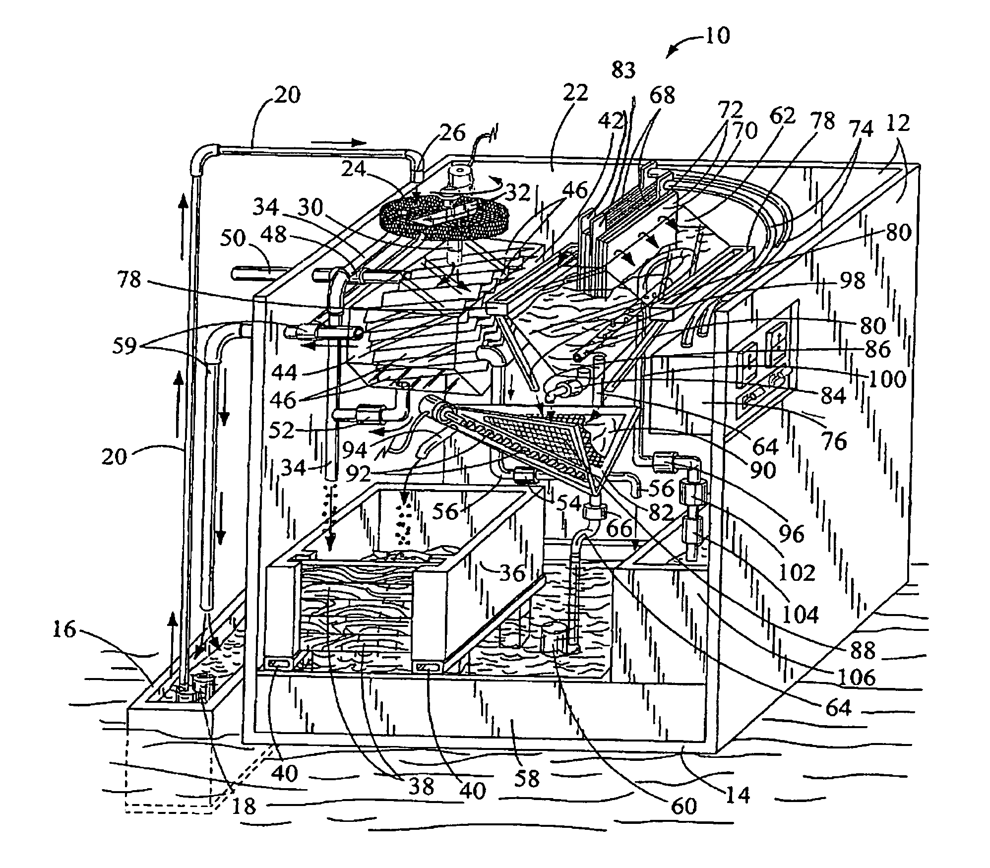
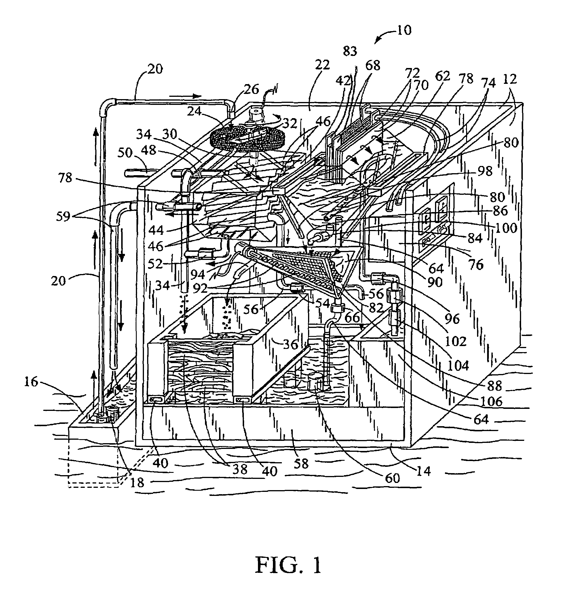
[0025]In FIG. 1, a perspective view of the individual components making up the subject electrocoagulation waste water batch tank treatment system is illustrated. The overall treatment system has a general reference numeral 10. As mentioned above, the system 10 is used for treating and cleaning waste water circulated through the components mounted in a batch tank 12. The front and the top of the tank 12 have been cutaway for ease in viewing the individual components mounted therein. The batch tank is designed to typically treat 50 to 2500 gallons of waste water and can have dimensions in a range of 2 to 8 feet in width, 4 to 24 feet in length and 4 to 10 feet in height. A bottom 14 of the tank 12 can be adapted for mounting on skids for ease in transporting the unit from one location to another and treating different sources of water.

[0026]In this drawing, waste water is received in a waste water sump 16 or a buried waste tank next to the batch tank 12. Obviously, the waste water can...


PUM

PropertyMeasurementUnit
lengthaaaaaaaaaa
widthaaaaaaaaaa
widthaaaaaaaaaa

Abstract

A waste water treatment system and process for treating waste water received in a batch tank. The waste water is discharged in a headwork screen for removing large solids in the water. The solids are into a sludge drying bin. The screened water is transferred into a top of an influent surge tank with an oil/water separator. The oil/water separator includes a plurality of coalescing plates for separating free oil from the waste water. Heavy solids in the surge tank are drained into the sludge drying bin. The waste water is now dropped into a containment pan. From the containment pan, the waste water is pumped into a water treatment tank. The water treatment tank includes two or more electrodes mounted in the top thereof. The electrodes are separated using insulating support spacers for providing proper electrode spacing and insulation between the electrodes. The electrodes are used for providing current to the waste water and separating the contaminates in the water by electrocoagulation. The treated water in the water treatment tank is discharged after a completion of a period of settling or dwell time into a clean water tank.

Description

BACKGROUND OF THE INVENTION[0001](a) Field of the Invention[0002]This invention relates to a system and a process for treating influent waste water and more particularly, but not by way of limitation, to an electrocoagulation waste water batch tank treatment system and process for greatly reducing various types of contaminates held in suspension in the waste water.[0003](b) Discussion of Prior Art[0004]The evolution of electrocoagulation is driven by a need to make waste water treatment processes more efficient. Recent increases in electrical costs and metal have changed the goals from optimum treatment efficiency to reduced operating costs. Many of the exotic configurations requiring specific electrode materials have given way to trying to utilize available stock material. New ideas have helped reduce electrode costs, but still there is a need for a more versatile, more flexible, standard design using inexpensive materials and components. The subject invention disclosed herein atte...

Claims


Application Information

Patent Timeline
Patent Type & Authority Patents(United States)
IPC IPC(8): C02F1/40C02F1/463
CPCB01D17/0211C02F1/463C02F9/00C02F1/001C02F1/20
Inventor HERBST, ROBERT J.
Owner H2O TECH
Why Eureka
Try Eureka