Indirect spot welding method

a welding method and indirect spot technology, applied in welding/soldering/cutting articles, other domestic objects, manufacturing tools, etc., can solve the problems of not not necessarily being effective for indirect spot welding, and not meeting control standards, etc., to achieve the effect of stably obtaining

Active Publication Date: 2011-11-10
JFE STEEL CORP
View PDF10 Cites 40 Cited by
  • Summary
  • Abstract
  • Description
  • Claims
  • Application Information

AI Technical Summary

Benefits of technology

[0033]The present invention makes it possible to stably obtain nuggets formed in a fused stat...

Problems solved by technology

The technique disclosed in PTL 1 may be effective for series spot welding, but may not be effective for indirect spot welding which involves a different welding method.
The technique disclosed in PTL 2 may also be effective for series spot welding, but may not necessarily be effective for indirect spot welding.
Additionally, this technique is disadvantag...

Method used


Image

  • Indirect spot welding method
  • Indirect spot welding method
  • Indirect spot welding method

Examples


Embodiment Construction

[0037]Hereinafter, the present invention will be specifically described with reference to exemplary embodiments selected for illustration in the drawings.

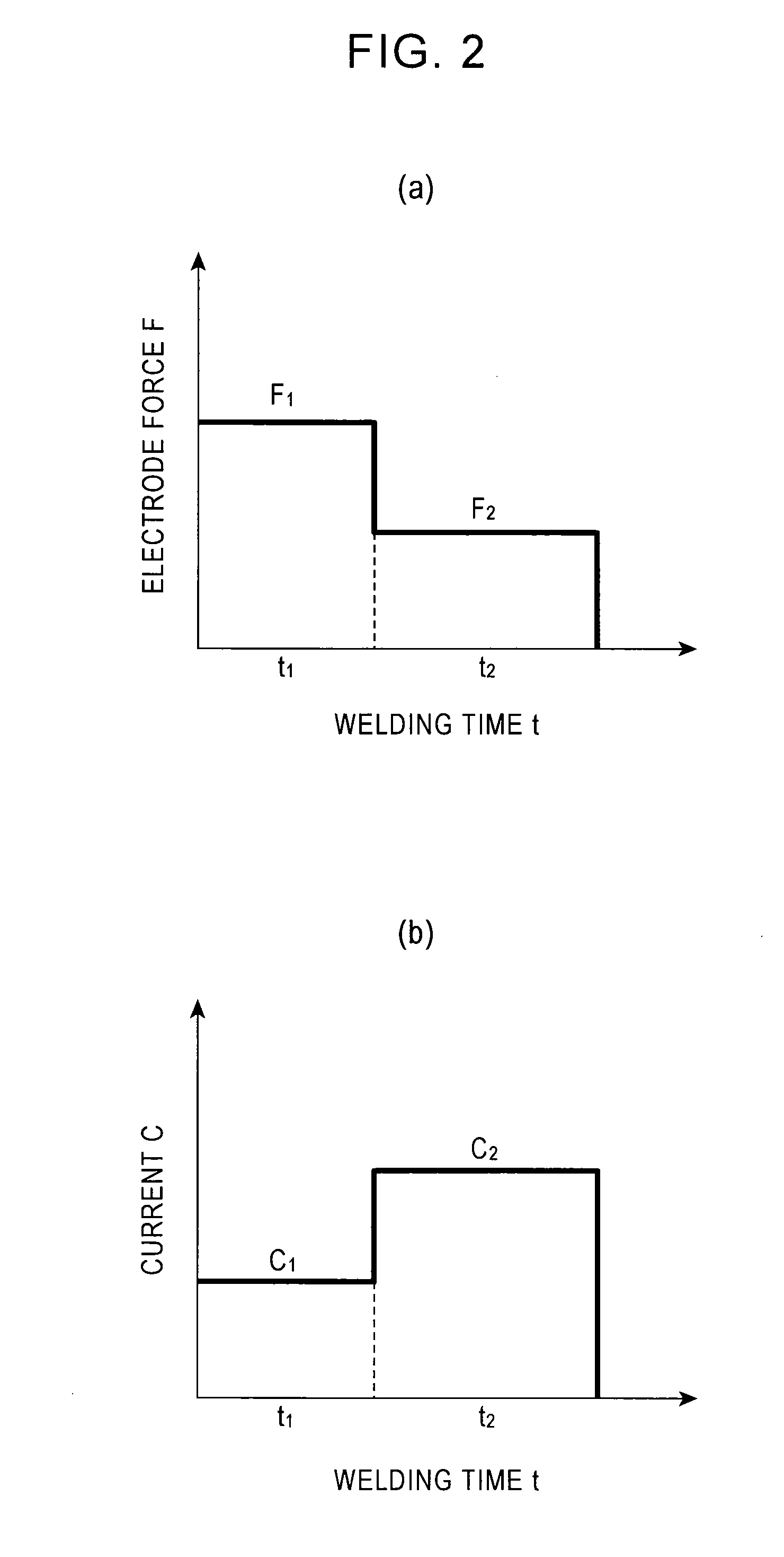
[0038]FIG. 2(a) illustrates a basic relationship between welding time and electrode force, and FIG. 2(b) illustrates a basic relationship between welding time and current, both according to embodiments of the present invention.

[0039]In an embodiment of the present invention, for electrode force and current, the time from turning on electricity is simultaneously or independently divided into two time periods, in each of which one or both of electrode force F and current C is or are controlled. When one of electrode force F and current C is to be controlled, time periods obtained by dividing the time from turning on electricity are denoted by t1 and t2. When both electrode force F and current C are to be independently controlled, time periods for electrode force F are denoted by tF1 and tF2 and time periods for current C are denoted ...


PUM

PropertyMeasurementUnit
Timeaaaaaaaaaa
Timeaaaaaaaaaa
Timeaaaaaaaaaa

Abstract

An indirect spot welding method is provided in which, in indirect spot welding, nuggets formed in a fused state can be stably obtained. In the indirect spot welding method, the welding time is divided into two time periods t1 and t2, where electrode force F1 and current C1 are applied in the first time period t1, and electrode force F2 lower than electrode force F1 and current C2 higher than current C1 are applied in the next time period t2.

Description

CROSS-REFERENCE TO RELATED APPLICATIONS[0001]This application is the U.S. National Phase application of PCT International Application No. PCT / JP2010 / 051549, filed Jan. 28, 2010, and claims priority of Japanese Patent Application No. 2009-018809, filed Jan. 29, 2009, and Japanese Patent Application No. 2009-243650, filed Oct. 22, 2009, the disclosures of which PCT and priority applications are incorporated herein by reference in their entirety for all purposes.FIELD OF THE INVENTION[0002]The present invention relates to an indirect spot welding method in which a member composed of at least two overlapping metal sheets is welded by holding a spot welding electrode against the metal sheets while applying pressure to the spot welding electrode from one side of the member, attaching a feeding point to the metal sheet on the other side of the member at a location remote from the spot welding electrode, and allowing current to flow between the spot welding electrode and the feeding point.B...

Claims


Application Information

Patent Timeline
IPC IPC(8): B23K11/00
CPCB23K11/115B23K11/24B23K2201/18B23K2201/04B23K11/312B23K11/11B23K11/30B23K2103/04B23K2101/18B23K11/3009B23K2101/04
Inventor MATSUSHITA, MUNEOIKEDA, RINSEI
Owner JFE STEEL CORP
Why Eureka
Try Eureka