Aircraft with Helicopter Rotor, Thrust Generator and Assymetric Wing Configuration

a thrust generator and helicopter technology, applied in the field of helicopters, can solve the problems of blade stalling, blade stalling, loss of smooth laminar airflow over the surface of the blade, and the conventional helicopter, which offers drastically improved maneuverability over the airplan

Inactive Publication Date: 2011-11-10
CHALLIS DOUGLAS
View PDF8 Cites 32 Cited by
  • Summary
  • Abstract
  • Description
  • Claims
  • Application Information

AI Technical Summary

Benefits of technology

Powering the main helicopter rotor may provide the remaining half of the amount of vertical lift needed to maintain the altitude of the aircraft during forward flight on the opposite side of the fuselage.
Alternatively, flowing air around a wing extending laterally from the fuselage on the second side thereof, and powering the main helicopter rotor, together may provide substantially wholly the remaining half of the amount of vertical lift needed to maintain the altitude of the aircraft during forward flight.

Problems solved by technology

Conventional helicopters, while offering drastically improved maneuverability over airplanes, are limited to travelling at relatively low speeds.
Increasing the angle of attack too much will cause a blade to stall, as smooth laminar airflow over the surfaces of the blade is lost.
As a result, conventional helicopters are limited in their maximum speed as increasing the forward velocity leads to a need for increased angle of attack for retreating blades, and a high angle of attack will lead to stalling and a corresponding lack of lift.
The presence of large wings on opposite sides of these aircraft may decrease the efficiency of using the main rotor to create lift during vertical movement, hovering and the transition from hovering to forward flight as their surface area creates vertical drag.
A full wing span across two sides of the aircraft also increases the weight of the aircraft and the cost of its manufacture due to more material and assembly requirements.
The wings of a compound helicopter do not automatically eliminate all rotor related issues in forward flight.

Method used


Image

  • Aircraft with Helicopter Rotor, Thrust Generator and Assymetric Wing Configuration
  • Aircraft with Helicopter Rotor, Thrust Generator and Assymetric Wing Configuration
  • Aircraft with Helicopter Rotor, Thrust Generator and Assymetric Wing Configuration

Examples


first embodiment

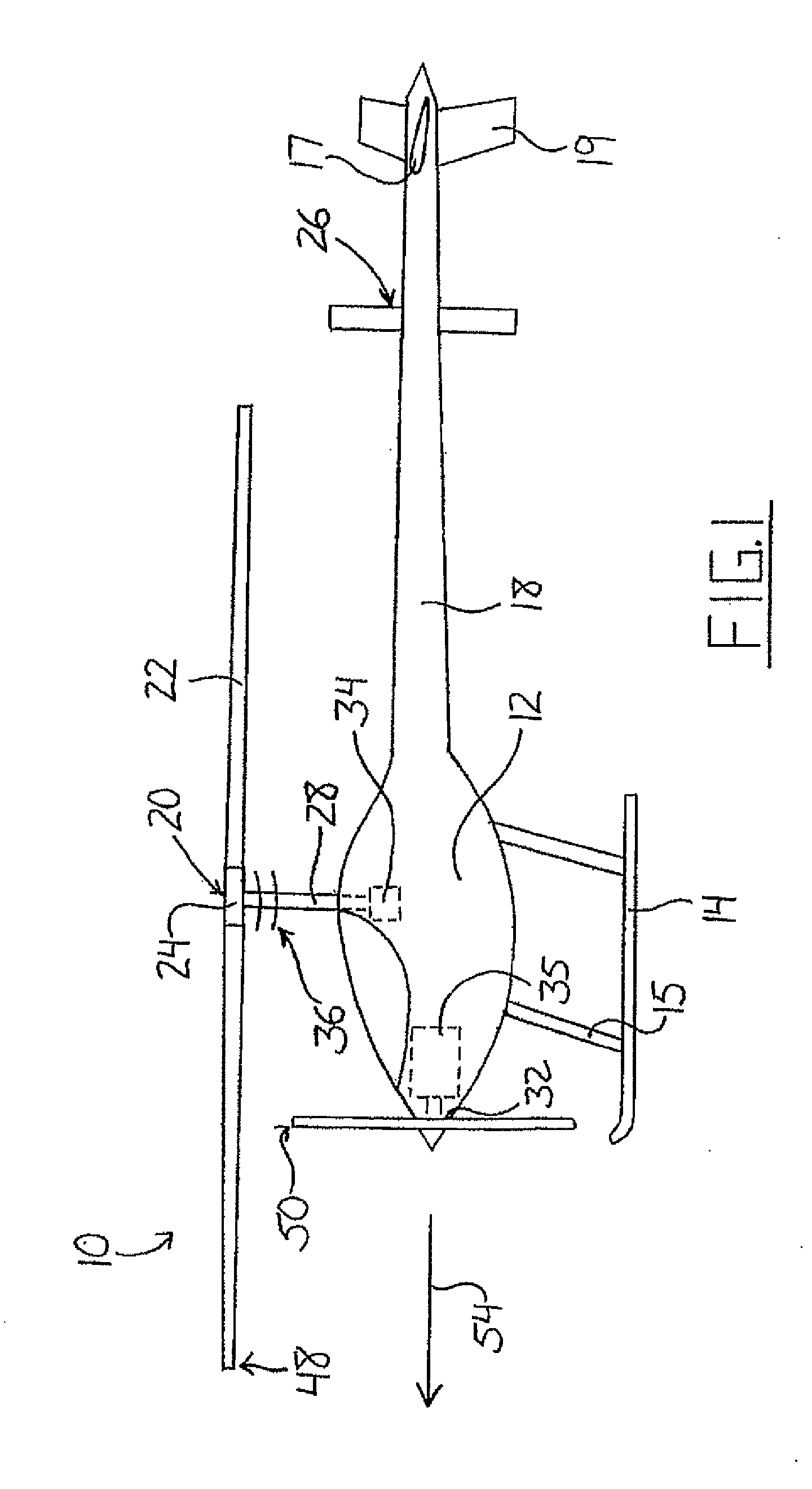
As shown in FIG. 1, the present invention features the propeller supported for rotation within a plane generally perpendicular to the plane of rotation of the main rotor. The aircraft may be flown such that the main rotor 20 rotates about a vertical axis, thereby providing only vertical lift. This differs from a conventional helicopter wherein the cyclic control is used to create more lift during a rear half of the main rotor's rotation nearest the tail than in a front half of the main rotor's rotation nearest the nose, thereby causing the helicopter to tilt nose down such that the rotation plane of the main rotor is angled from a horizontal orientation and its rotation axis is correspondingly angled from a vertical orientation. This cyclical action is combined with an increase in power and collective to the rotor. These actions angle and increase the force produced by the main rotor from a vertical direction such that both vertical lift and forward thrust components are created to ...

second embodiment

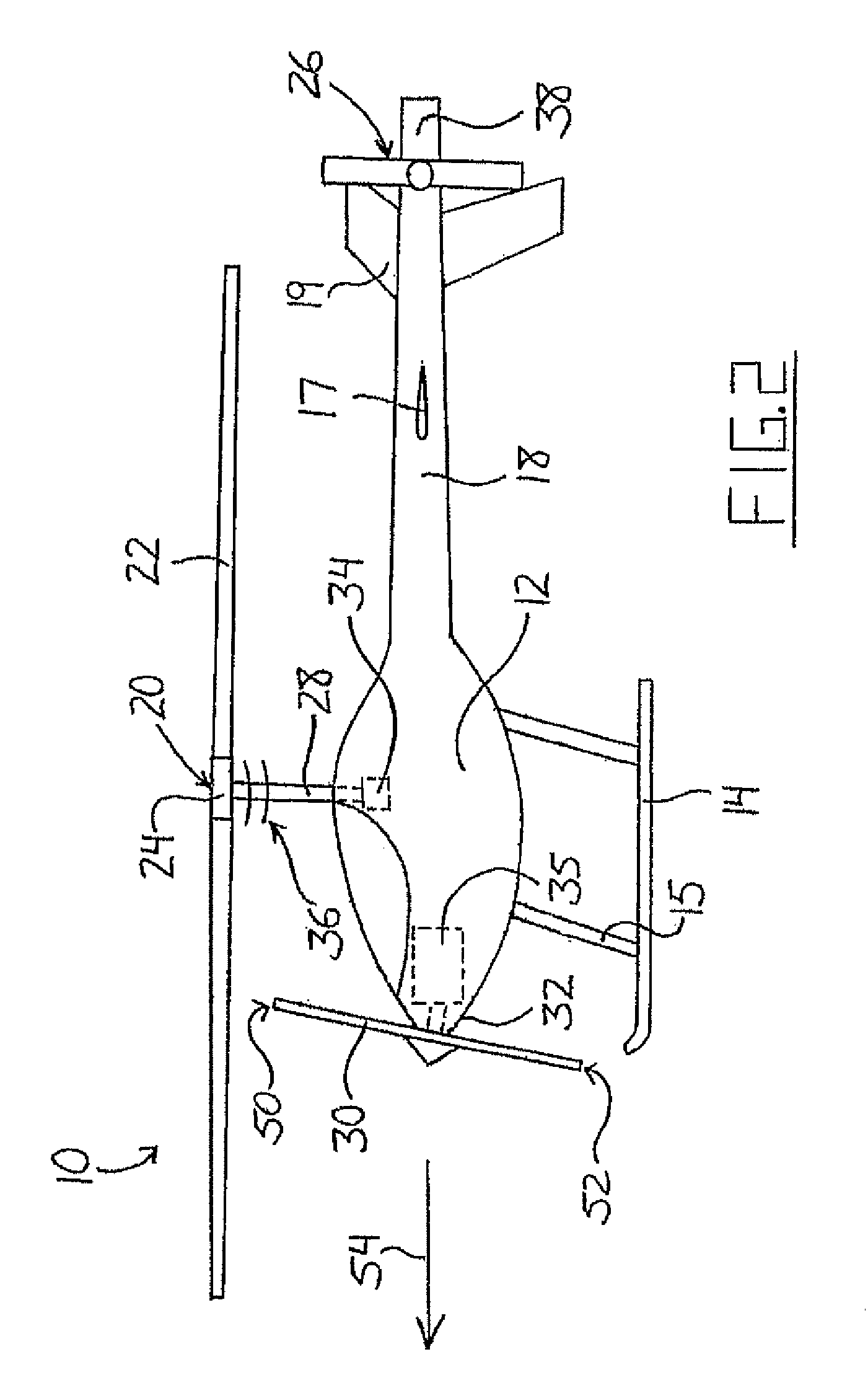
As seen in FIG. 2, the propeller 30 of the second embodiment is not mounted on the nose 32 so as extend in a vertical plane parallel to the main rotor shaft 28 and normal to a longitudinal axis of the fuselage 12. The propeller 30 is tilted rearward such that a lowest point in its rotation 52 is disposed forward of the highest point in its rotation 50. In other words, the axis of the propeller 30 has been rotated downward about its front end from a longitudinal axis of the fuselage 12 in a vertical plane by a small angle.

A radio controlled prototype of the second embodiment of the present invention was able to achieve forward speeds estimated at approximately twice what was attainable before the installation of the nose mounted propeller and a respective powerplant. However, the aircraft was somewhat difficult to control in its upper velocity range. It is contemplated however that control at these higher speeds may be improved with flight experience as the differences in flight char...

fifth embodiment

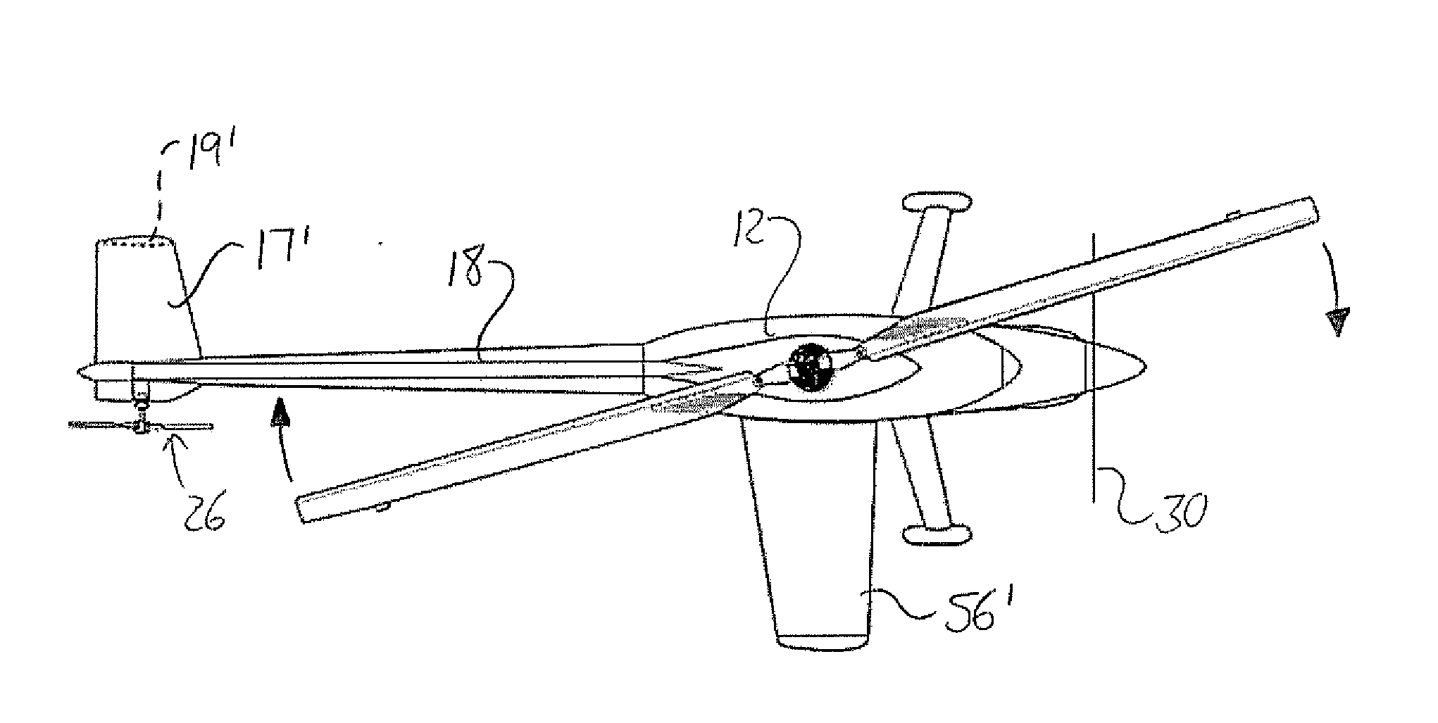
The fifth embodiment aircraft is piloted in the same manner the fourth embodiment. The main rotor, as viewed from above, rotates in the same one of a clockwise or counterclockwise direction as the propeller 30, as viewed from behind, and the rotational plane of the propeller is perpendicular to the longitudinal axis of the aircraft, and thus generally perpendicular to the rotational plane of the main rotor. The main helicopter rotor is driven at all times during flight to provide lift regardless of the aircraft's attained velocity, even at high speed forward cruising where forward thrust is provided by the propeller 30 instead of the main rotor, unlike prior art compound helicopters where the rotor is unloaded at higher speeds to rely on a large wing span on both sides of the fuselage for sufficient lift. The single primary wing 56′ on the retreating blade side of the fuselage creates a degree of wing-provided lift that is unmatched on the opposite advancing-blade side of the fusela...


PUM


Abstract

An aircraft features a source of forward thrust on a fuselage having a helicopter rotor assembly and an asymmetric primary wing configuration providing more wing-generated lift on one side of the fuselage than the other. The primary wing configuration counteracts the rotor's dissymmetry of lift during forward cruising, and reliance on the separate thrust source for such cruising reduces demand on the main rotor, keeping the angle of attack on the rotor blades low to avoid the stalling and violent vibration experienced by conventional helicopters at relatively high speeds. In some embodiments, an oppositely asymmetric tail wing or horizontal stabilizer acts alone, or together with an offset vertical stabilizer laterally outward from the tail, to counteract yaw-inducing drag of the primary wing.

Description

FIELD OF INVENTIONThe present invention relates to a rotor aircraft and more particularly to such an aircraft employing cooperation of a helicopter rotor, thrust generator and asymmetric wing configuration to achieve greater cruising speed that conventional helicopters.BACKGROUNDConventional helicopters, while offering drastically improved maneuverability over airplanes, are limited to travelling at relatively low speeds. During vertical motion or hovering, the helicopter is oriented horizontally such that the main rotor is driven for rotation about a generally vertical axis to create lift. To achieve forward motion, extra power is applied, collective pitch is increased and the helicopter is tilted nose down out of the horizontal orientation by adjusting the cyclic pitch to increase the angle of attack of the rotor blades during a portion of their rotation in which they extend rearward from the hub, thereby create more lift near the rear of the aircraft. With the aircraft in this ti...

Claims


Application Information

Patent Timeline
Patent Type & Authority Applications(United States)
IPC IPC(8): B64C27/26
CPCB64C2027/8281B64C27/26B64C39/029
Inventor CHALLIS, DOUGLAS
Owner CHALLIS DOUGLAS
Why Eureka
Try Eureka