DISCRETE CO-FLOW JET (dCFJ) AIRFOIL

a co-flow jet and airfoil technology, applied in the direction of air-flow influencers, machines/engines, transportation and packaging, etc., to achieve the effect of reducing aircraft complexity, high-performance co-flow, and increasing performance and efficiency

Active Publication Date: 2011-09-01
UNIV OF MIAMI
View PDF25 Cites 34 Cited by
  • Summary
  • Abstract
  • Description
  • Claims
  • Application Information

AI Technical Summary

Benefits of technology

[0005]The present invention advantageously provides a system for an aircraft having an integrated propulsion and lift generating system and a method of operation, thereby reducing aircraft complexity, and greatly increasing performance and efficiency. In particular, the present invention may provide an aircraft having one or more fixed wings in a flying wing configuration, where the aircraft further includes a high performance co-flow jet (CFJ) airfoil to produce both lift and thrust rather than a conventional propulsion system (i.e., a propeller or jet engine). As a result, the energy expenditure is significantly reduced compared to that of a conventionally powered aircraft, as the energy consumption is largely limited to the power to provide a fluid flow across a portion of the aircraft, which does not necessarily require a combustion device. In addition, the maneuverability and safety of the aircraft is further enhanced due to the increased stall margin of the CFJ airfoil.

Problems solved by technology

As a result, the energy expenditure is significantly reduced compared to that of a conventionally powered aircraft, as the energy consumption is largely limited to the power to provide a fluid flow across a portion of the aircraft, which does not necessarily require a combustion device.

Method used


Image

  • DISCRETE CO-FLOW JET (dCFJ) AIRFOIL
  • DISCRETE CO-FLOW JET (dCFJ) AIRFOIL
  • DISCRETE CO-FLOW JET (dCFJ) AIRFOIL

Examples


Embodiment Construction

[0040]It will be appreciated by persons skilled in the art that the present invention is not limited to what has been particularly shown and described herein above. In addition, unless mention was made above to the contrary, it should be noted that all of the accompanying drawings are not to scale. A variety of modifications and variations are possible in light of the above teachings without departing from the scope and spirit of the invention, which is limited only by the following claims.

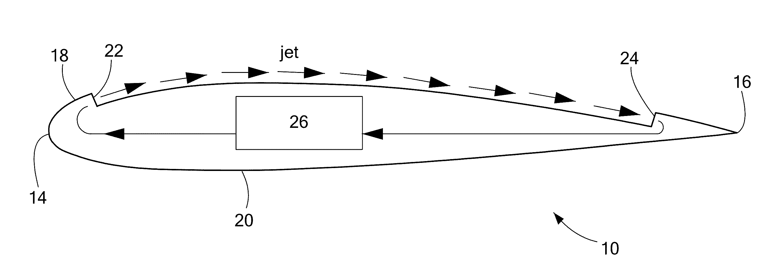
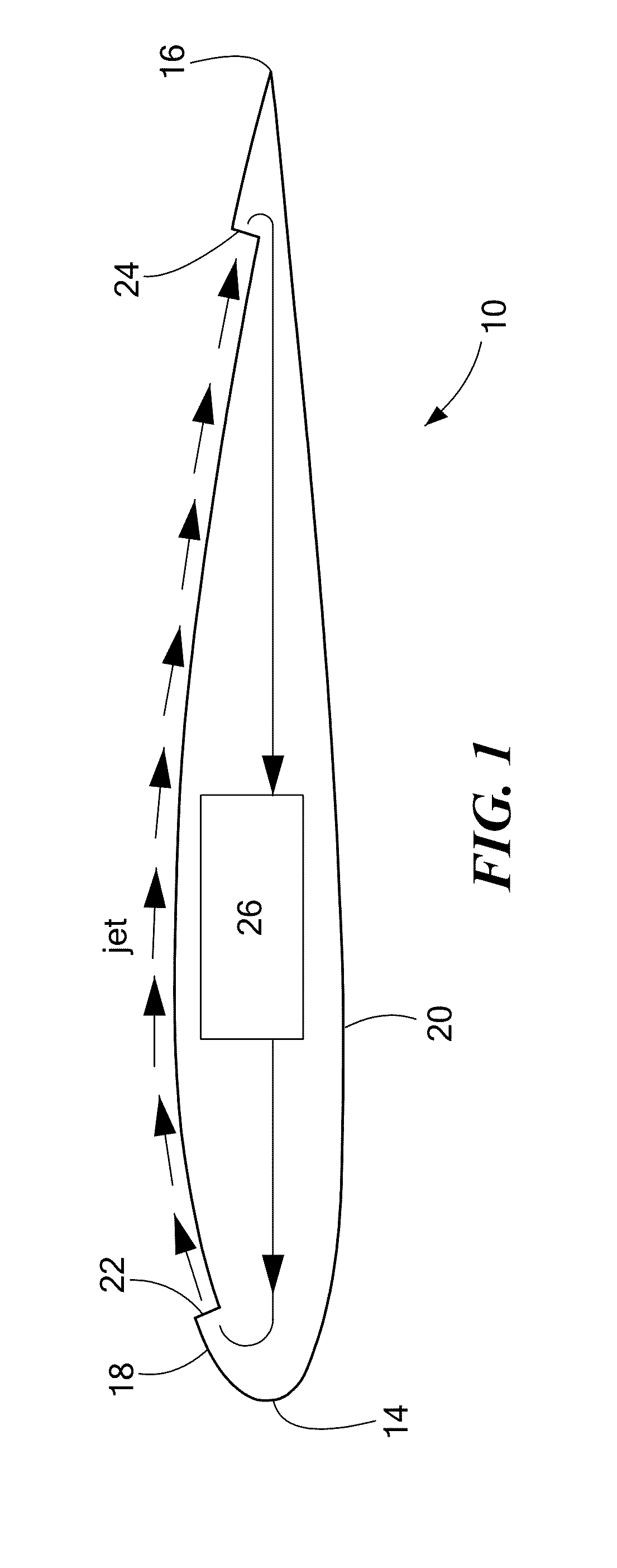
[0041]The present invention advantageously provides an aircraft having an integrated propulsion and lift generating system, thereby reducing aircraft complexity, and greatly increasing performance and efficiency. In particular, the present invention may provide an aircraft having one or more fixed wings in a flying wing configuration, where the aircraft further includes a high performance co-flow jet (CFJ) circulating about at least a portion of an aircraft surface to produce both lift and thrust ...


PUM


Abstract

The present invention provides an aircraft having one or more fixed wings in a flying wing configuration, where the aircraft further includes a high performance co-flow jet (CFJ) circulating about at least a portion of an aircraft surface to produce both lift and thrust.

Description

CROSS-REFERENCE TO RELATED APPLICATION[0001]This application is a continuation-in-part-of U.S. utility application Ser. No. 12 / 119,193, filed May 12, 2008, entitled CO-FLOW JET AIRCRAFT, which is a continuation-in-part-of PCT Application Serial No. PCT / US07 / 10122, filed Apr. 24, 2007, entitled EMISSIONLESS SILENT AND ULTRA-EFFICIENT AIRPLANE USING CFJ AIRFOIL, which is related to and claims priority to U.S. Provisional Patent Application Ser. No. 60 / 796,042, filed Apr. 28, 2006, entitled ENGINELESS EMISSIONLESS SILENT AND ULTRA-EFFICIENT AIRPLANE USING CFJ AIRFOIL; this application is also a continuation-in-part-of U.S. Utility patent application Ser. No. 11 / 064,053, filed Feb. 23, 2005, entitled HIGH PERFORMANCE AIRFOIL WITH CO-FLOW JET FLOW CONTROL, which is related to and claims priority to U.S. Provisional Patent Application Ser. No. 60 / 603,212, filed Aug. 20, 2004, entitled HIGH PERFORMANCE AIRFOIL WITH CO-FLOW JET FLOW CONTROL, the entirety of all of which is incorporated here...

Claims


Application Information

Patent Timeline
Patent Type & Authority Applications(United States)
IPC IPC(8): B64C21/04B64C21/06F01D5/12
CPCB64C21/025Y02T50/166Y02T50/12B64C2039/105Y02T50/10
Inventor ZHA, GECHENGDANO, BERTRAND P.E.
Owner UNIV OF MIAMI
Why Eureka
Try Eureka