Electrical Generator With Improved Cooling And Exhaust Flows

a technology of electric generators and exhaust flows, applied in the direction of machines/engines, mechanical energy handling, mechanical equipment, etc., can solve the problems of electrical generators that provide less electrical power, electrical generators that are unappealing aesthetically, electrical generators that are inoperable, etc., to reduce the size, or the effect of footprint, softening the view, and facilitating “hiding

Inactive Publication Date: 2011-11-10
GENERAC POWER SYSTEMS
View PDF7 Cites 18 Cited by
  • Summary
  • Abstract
  • Description
  • Claims
  • Application Information

AI Technical Summary

Benefits of technology

[0005]One of the challenges faced by engineers in designing smaller electrical generators without sacrificing power output is preventing overheating of various temperature sensitive components of the electrical generator. If these components are not cooled effectively, the components may fail and render the electrical generator inoperative. While effective in providing thermal control, heat sinks, fans, and coolant circulations systems can ultimately add to the size of the electrical generator and, in the case of using multiple or larger fans, greater noise emissions.
[0007]The present invention is directed to a fuel powered, electrical generator and, more particularly, to a vertical fuel powered, electrical generator. The invention provides an electrical generator having a smaller footprint than conventional horizontal generators and has a unique frame construction that allows for easier access to the components of the electrical generator, such as for maintenance, service, and repair. Additionally, in accordance with one embodiment of the invention, the electrical generator has an internal combustion engine with a crankcase that is configured in a manner that allows the alternator of the electrical generator to be mounted directly to the crankcase. In this embodiment, the invention avoids the need for a separate mount or similar member that is otherwise typically used to couple the alternator to the engine. Furthermore, as will be described more fully below, the present invention provides an electrical generator having improved airflow characteristics for better thermal control.

Problems solved by technology

Many consumers find the electrical generator aesthetically unappealing and, as such, will often place the electrical generator in a location that is hidden from view altogether or use various plantings, e.g., shrubs, around the electrical generator to soften its view.
Decreasing the size, or footprint, of the electrical generator would make it easier to “hide” the electrical generator; however, reducing the size of the electrical generator can result in an electrical generator that provides less electrical power.
One of the challenges faced by engineers in designing smaller electrical generators without sacrificing power output is preventing overheating of various temperature sensitive components of the electrical generator.
If these components are not cooled effectively, the components may fail and render the electrical generator inoperative.
While effective in providing thermal control, heat sinks, fans, and coolant circulations systems can ultimately add to the size of the electrical generator and, in the case of using multiple or larger fans, greater noise emissions.
That is, the components of conventional electrical generators will typically be contained within an integrated, and often heavy, housing that is difficult for a consumer to disassemble or remove to access the components of the electrical generator, such as for inspection, maintenance, and service.
In both instances, servicing or repairing the electrical generator can be difficult for those of conventional design.

Method used


Image

  • Electrical Generator With Improved Cooling And Exhaust Flows
  • Electrical Generator With Improved Cooling And Exhaust Flows
  • Electrical Generator With Improved Cooling And Exhaust Flows

Examples


Embodiment Construction

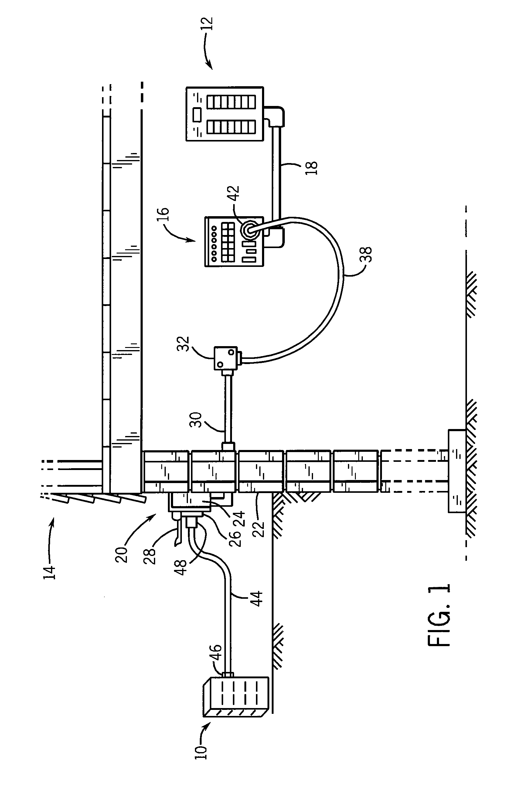
[0023]FIG. 1 shows a power inlet arrangement for interconnecting an electrical generator 10 with a main electrical panel or load center 12 located in the interior of a building 14. In the power inlet arrangement of FIG. 1, a power transfer panel 16 is mounted adjacent main panel 12, and is interconnected therewith via a series of wires enclosed by a conduit 18 extending between main panel 12 and transfer panel 16.

[0024]A power inlet box 20 is mounted to the wall of building 14, shown at 22. Power inlet box 20 includes an external housing including a series of walls such as 24, and a receptacle 26 mounted to a front wall of the housing. A cover 28 is mounted to the front wall of the housing via a hinge structure, and is movable between an open position as shown in FIG. 1 and a closed position in which cover 28 encloses receptacle 26 when not in use. A conduit 30 extends between inlet box 20 and a junction box 32, and a flexible cord 38 is attached at one end to junction box 32. At it...


PUM


Abstract

An electrical generator has an internal combustion engine and an alternator mounted to the engine and operative to generate electrical power during running of the engine. The alternator and the engine are arranged vertically to reduce the footprint of the electrical generator. The components of the electrical generator are contained within an enclosure defined by a base panel, a set of upright side panels, and a roof panel. When the roof panel is removed, each of the side panels can be independently removed from engagement with the base panel, which allows for easier access to the components of the electrical generator, such as for maintenance, service, and repair. The components are arranged so that cooling and exhaust air flow paths are defined within the enclosure.

Description

CROSS-REFERENCE TO RELATED APPLICATION[0001]This application claims the benefit of U.S. Ser. No. 61 / 295,961 filed Jan. 18, 2010, the disclosure of which is incorporated herein by reference.BACKGROUND AND SUMMARY OF THE INVENTION[0002]Electrical generators are used in a wide variety of applications. Typically, an electrical generator operates in a stand-by mode wherein the electrical power provided by a utility is monitored such that if the commercial electrical power from the utility fails or is otherwise interrupted for a certain period of time, the engine of the electrical generator is started, either automatically or manually by a customer, causing the electrical generator to supply emergency or backup electrical power. More particularly, the engine drives an alternator to provide electrical current to power selected electrical loads that are connected to the electrical generator, which is typically though a dedicated electrical panel, i.e., transfer panel.[0003]When the electric...

Claims


Application Information

Patent Timeline
Patent Type & Authority Applications(United States)
IPC IPC(8): H02K7/18H02K9/02
CPCF02B63/044F02B63/04
Inventor RICHARDSON, CHRISTINEBECHTEL, MICHAELWRAY, JOELGOHDE, JONATHANBRANDENBURG, BILLYPILLING, LEONARD
Owner GENERAC POWER SYSTEMS
Why Eureka
Try Eureka