Parallel Boost Unity Power Factor High Power Battery Charger

a high-power battery charger and unity power factor technology, applied in the field of power electronics, can solve the problems of large amount of power dissipation on the charger itself, waste of power, difficult thermal management, etc., and achieve the effects of high power factor, high efficiency and high power factor

Inactive Publication Date: 2011-11-10
JIN NORMAN LUWEI
View PDF7 Cites 14 Cited by
  • Summary
  • Abstract
  • Description
  • Claims
  • Application Information

AI Technical Summary

Benefits of technology

[0008]The present invention is a design for a high power battery c

Problems solved by technology

There exist major requirements on such high power battery chargers.1) The high power level involved in electrical vehicle charging means that the system must operate at high efficiency, as a small decline in efficiency will result in large amounts of power dissipation on the charger itself.
This wasted power leads to difficult thermal management, especially in an on-board charger.2) Unity power factor or power factor close to 1 shall be maintained.
The main challenge to a unity power factor charger is that the voltage of the battery itself nullifies charging voltage less than the current battery voltage.
This only allows the battery to be charged in a very narrow time window, cal

Method used


Image

  • Parallel Boost Unity Power Factor High Power Battery Charger
  • Parallel Boost Unity Power Factor High Power Battery Charger
  • Parallel Boost Unity Power Factor High Power Battery Charger

Examples


Embodiment Construction

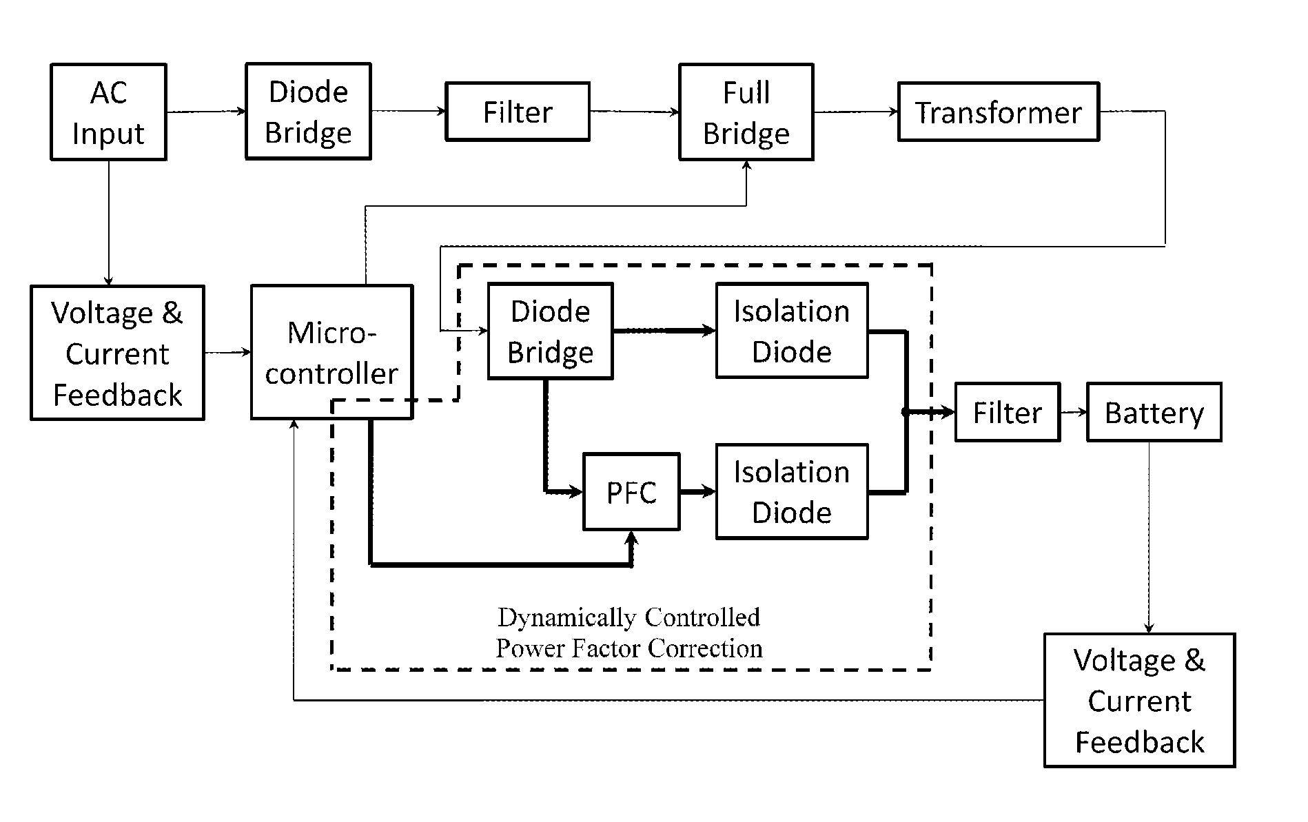
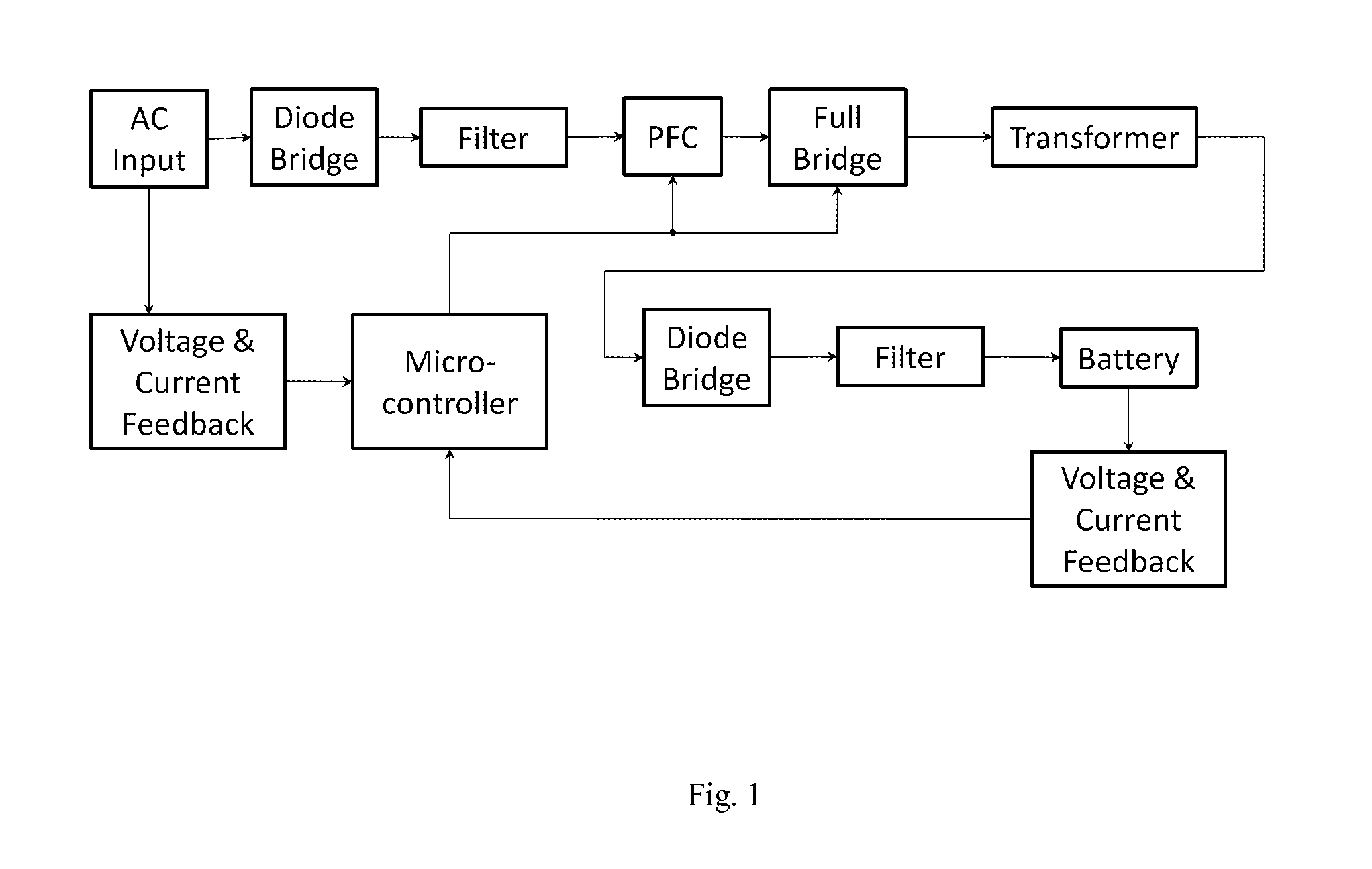
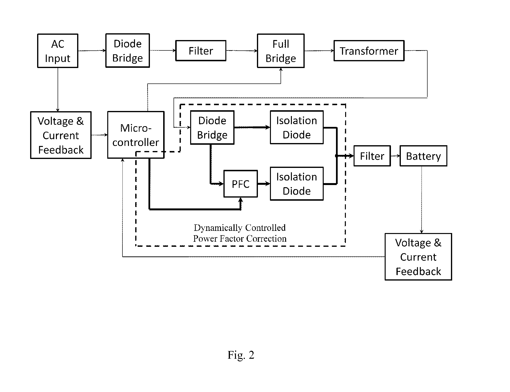
[0013]Referring to the invention in more details in FIGS. 1 and 2, note that the main difference between the present invention (FIG. 2) and a typical full power PFC design (FIG. 1) is the location of the power factor correction circuit. The power factor circuit in the present invention is placed in parallel with a bypassing diode, at the output of the full bridge converter. This change allows the dynamic control of whether or not the charging current passes through the power factor correction circuit. Furthermore, the power factor circuit will only be activated when necessary to facilitate charging of the battery, minimizing the amount of power that must pass through the power factor correction circuit.

[0014]The present invention brings many production advantages over a typical full power PFC design. Unlike the full power PFC booster in the conventional two stage designs (a PFC booster followed by a full bridge DC / DC converter), the dynamic PFC circuit in this invention, as a partia...


PUM


Abstract

A high power battery charger includes a full bridge DC/DC converter as its main converter following a low frequency diode rectifier bridge connected to the power grid and followed by a high frequency diode rectifier bridge to charge the battery. Because the battery negates charging voltage less than that of itself, the conduction angle of the charging current dramatically drops when the battery voltage increases. The small conduction angle of the charger raises peak current and lowers power factor. An active power factor correction circuit for a high power charger consists of a boost DC/DC converter placed in conjunction with the main full bridge DC/DC converter. The present invention is a new charger topology that alters the positioning and control of the power factor correction circuit, minimizing the impact of the required additional power factor correction booster on the high power charger's overall efficiency, cost, weight and size.

Description

BACKGROUND OF INVENTION[0001]The present invention is in the technical field of power electronics. More specifically, the present invention is in the technical field of high power battery chargers. The invention was created with the original objective of charging batteries in plug-in hybrid or battery powered electric vehicles. These vehicles that feature long range per charge and fast charging capabilities necessitate high power battery chargers.[0002]There exist major requirements on such high power battery chargers.[0003]1) The high power level involved in electrical vehicle charging means that the system must operate at high efficiency, as a small decline in efficiency will result in large amounts of power dissipation on the charger itself. This wasted power leads to difficult thermal management, especially in an on-board charger.[0004]2) Unity power factor or power factor close to 1 shall be maintained. A power factor correction (PFC) circuit is required in a charger design. Ba...

Claims


Application Information

Patent Timeline
IPC IPC(8): H02J7/10
CPCH02M1/4225Y02B40/90Y02B70/126H02J7/022H02J7/02H02J2207/20Y02B40/00Y02B70/10
Inventor JIN, NORMAN LUWEI
Owner JIN NORMAN LUWEI
Why Eureka
Try Eureka