
Recognition and pose determination of 3D objects in 3D scenes

a 3d object and pose technology, applied in the field of machine vision systems, can solve the problems of inability to recognize and localize 3d objects in 3d scenes, inability to implement local descriptors in real-time systems, and inability to accurately match scene and object correspondences, etc., to achieve low computation time, low cost, and robust to noise

Active Publication Date: 2011-11-10
MVTEC SOFTWARE
View PDF1 Cites 38 Cited by
  • Summary
  • Abstract
  • Description
  • Claims
  • Application Information

AI Technical Summary

Benefits of technology

The presented method has several advantages over previous methods: It allows the recognition of free-form objects with any kind of surface geometry and is thus not limited to objects of a certain type. Additionally, the method is robust to noise, missing object parts, and clutter. The pose of the 3D object is determined with high accuracy. The finding of the 3D object and the recovery of its 3D pose requires little computation time, and is suitable to real-time environments.
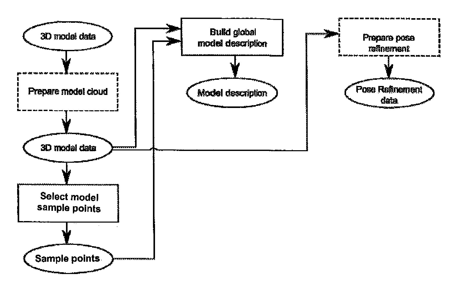
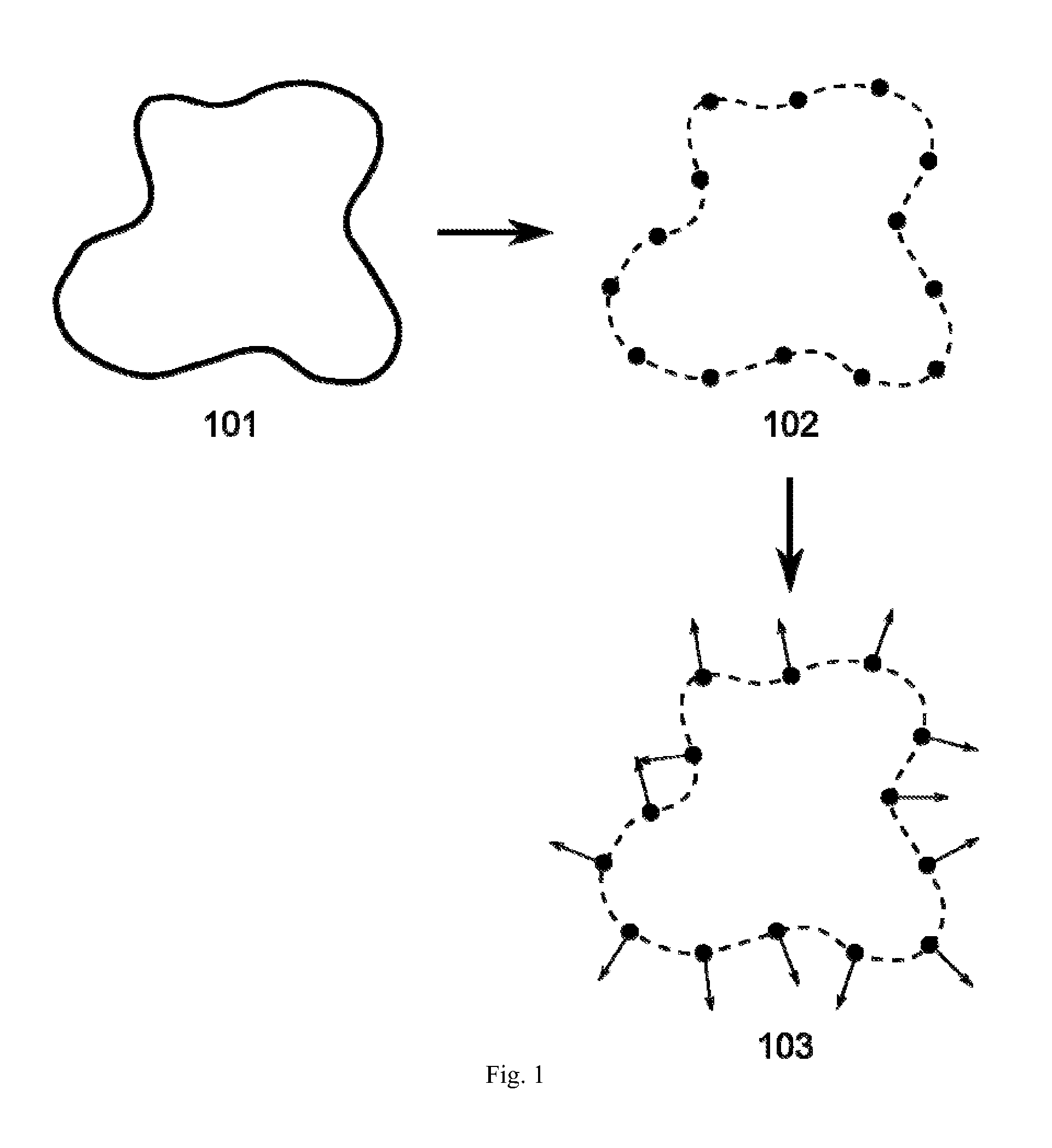
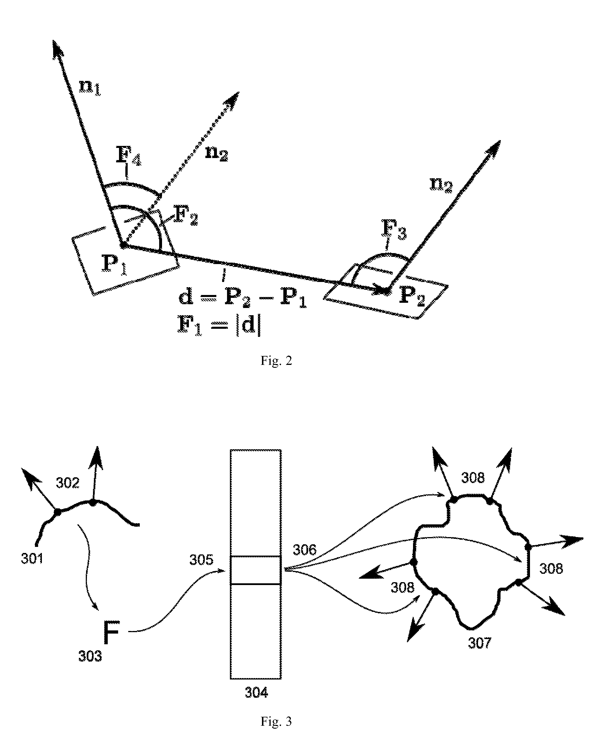
The method comprises two phases. In the offline-phase, a model description is computed that can later be used for finding the 3D object. The user needs to provide a 3D representation of the object to be found, e.g. a 3D CAD model or a set of 3D points. The method requires only the geometric shape of the object. No color, texture or surface reflectance information is required, making the invention suitable for a large range of object types. Additional local information, such as color and texture, may be provided to further increase the robustness of the method. The model description is built by sampling the object's surface at a certain rate, computing a descriptor for each pair of points from the sampled surface and storing the point pairs in a database that is indexed by said point pair descriptor.
Preferably, the 3D object data and / or the 3D scene data is filtered before processing comprising at least one of the steps of detecting and removing outliers; reducing noise; computing the surface normals.

Problems solved by technology

Several drawbacks are associated with approaches that rely on correspondence search with local descriptors: First, local descriptors cannot discriminate between similar surface parts on an object, such as larger planar patches.
Such similar parts lead to equal or similar local descriptors and in turn to incorrect correspondences between the scene and the object.
Increasing the radius of influence such that non-similar surface parts are included in the construction of the descriptor leads to sensitivity against missing parts of the surface, which are frequent in case of occlusion or sensor problems.
Second, local descriptors are typically too slow to be implemented in real-time systems and require processing times of several seconds.
Third, local descriptors are sensitive to clutter, i.e. scene parts that do not belong to the object of interest.
Furthermore, local descriptors require a dense representation of the 3D scene data, which is often not available.
Finally, the present descriptors are not fast enough for real-time applications.
All methods that rely on geometric primitives have the disadvantage that they do not work with general free-form objects.
However, all range image based systems are limited to the 3D information acquired from a single range image and cannot cope with general 3D information from other 3D sensors or from the combination of different range images.
Additionally they are not fast enough for real-time systems, as they typically require a brute-force search in the parameter space.
The major disadvantage of pose refinement is that the input pose needs to be close enough to the correct pose or otherwise the methods will fail to converge.
Good approximates of the correct pose are, however, difficult to obtain for 3D scenes that in practical applications often contain clutter, occlusion and noise.

Method used


Image

  • Recognition and pose determination of 3D objects in 3D scenes
  • Recognition and pose determination of 3D objects in 3D scenes
  • Recognition and pose determination of 3D objects in 3D scenes

Examples


Embodiment Construction

Denotations and Definitions

All of the following data is supposed to be available in electronic form, preferably digital. The methods and algorithms described are considered to be in electronic form and computer implemented.

In the following notation, a 3D point is a point in 3D space that has three coordinate values. Each 3D point refers to a coordinate system, with the most notably coordinate systems being the scene coordinate system where the 3D scene data is defined, and the object coordinate system where the 3D object of interest is defined. A 3D vector is a vector in 3D space that has three coordinate values. A 3D normal vector at a point on a surface is a vector in 3D that has an Euclidian length of 1 and that is perpendicular to the surface at the given point. A 3D point cloud is a set of 3D points. An oriented 3D point cloud is a 3D point cloud where a 3D normal vector is associated with each point. A 3D rigid transformation is a mapping of 3D points to 3D points that preserv...


PUM


Abstract

The invention provides a method for recognizing instances of a 3D object in 3D scene data and for determining the 3D poses of said instances comprising the following steps: (a) providing 3D scene data; (b) selecting at least one reference point from the 3D scene data; (c) computing, for each selected reference point, pose candidates for the 3D object under the assumption that said reference point is part of the 3D object; and (d) computing a set of filtered poses from the pose candidates.

Description

CROSS-REFERENCE TO RELATED APPLICATIONSThis application claims priority to European Application No. 10 16 2266.0, filed May 7, 2010, which is incorporated herein by reference in its entirety.FIELD OF THE INVENTIONThis invention relates generally to machine vision systems, and more particularly, to the recognition and localization of 3D objects in 3D scenes.BACKGROUND OF THE INVENTION3D object recognition is part of many computer vision applications. Compared to image-based computer vision that deals with planar intensity images, 3D computer vision deals with three-dimensional information and is especially important where non-planar objects and surfaces need to be inspected or manipulated. Many different methods and sensors were developed for acquiring the 3D surface information of a scene. Many of those methods return a so-called range image, which is an image where the value at each point represents the distance of the scene surface from the camera. If the sensor is calibrated and ...

Claims


Application Information

Patent Timeline
Patent Type & Authority Applications(United States)
IPC IPC(8): G06T15/00
CPCG06K9/6211G06K9/00214G06V20/653G06V10/757
Inventor DROST, BERTRAM HEINRICHULRICH, MARKUS
Owner MVTEC SOFTWARE
Learn More