Lighting device, display device and television receiver

a technology of display device and light source, which is applied in the field of light source device, display device and television receiver, can solve the problem of thinning of image display devi

Active Publication Date: 2011-11-10
SHARP KK
View PDF4 Cites 39 Cited by
  • Summary
  • Abstract
  • Description
  • Claims
  • Application Information

AI Technical Summary

Benefits of technology

[0008]When the light guide member is deformed due to thermal expansion or contraction, the follow-up mechanism moves the light source in the arrangement direction in which the light source and the light entrance surface are arranged in response to the deformation of the light guide member. Therefore, a relative position between the light source and the light entrance surface is less likely to change in the arrangement direction. As a result, a rate of light that exits from the light source and enters through the light entrance surface and a rate of light that exits from the light exit surface remain stable. Therefore, brightness can be stabilized.

Problems solved by technology

As a result, the image display devices are becoming thinner.

Method used


Image

  • Lighting device, display device and television receiver
  • Lighting device, display device and television receiver
  • Lighting device, display device and television receiver

Examples


first embodiment

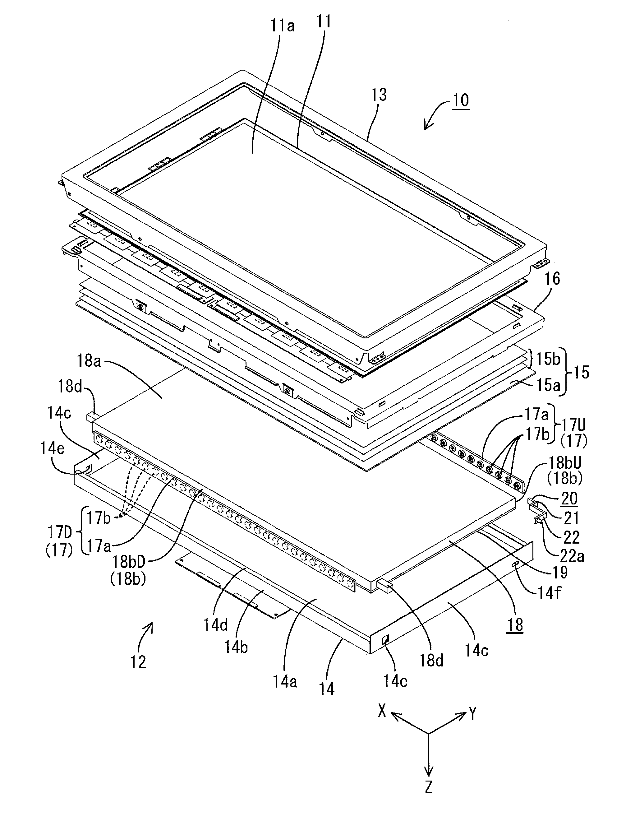
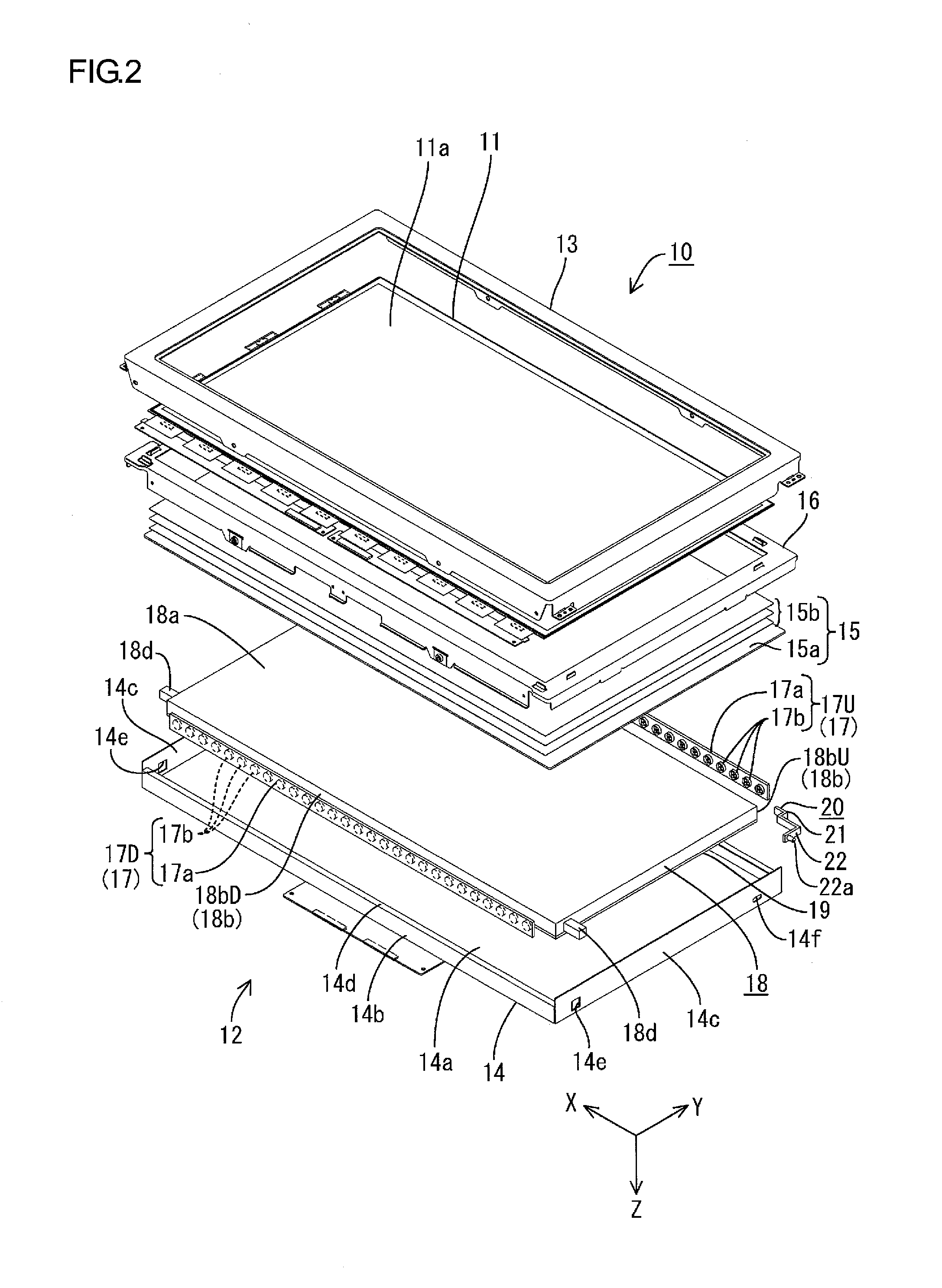
[0019]The first embodiment of the present invention will be explained with reference to FIGS. 1 to 6. In this embodiment, a liquid crystal display device 10 will be explained. X-axes, Y-axes and Z-axes in some drawings correspond to each other so as to indicate the respective directions. The X-axes and the Y-axes matches the horizontal direction and the vertical direction, respectively. In FIG. 2, the upper side and the lower side correspond to the front side and the rear side, respectively.

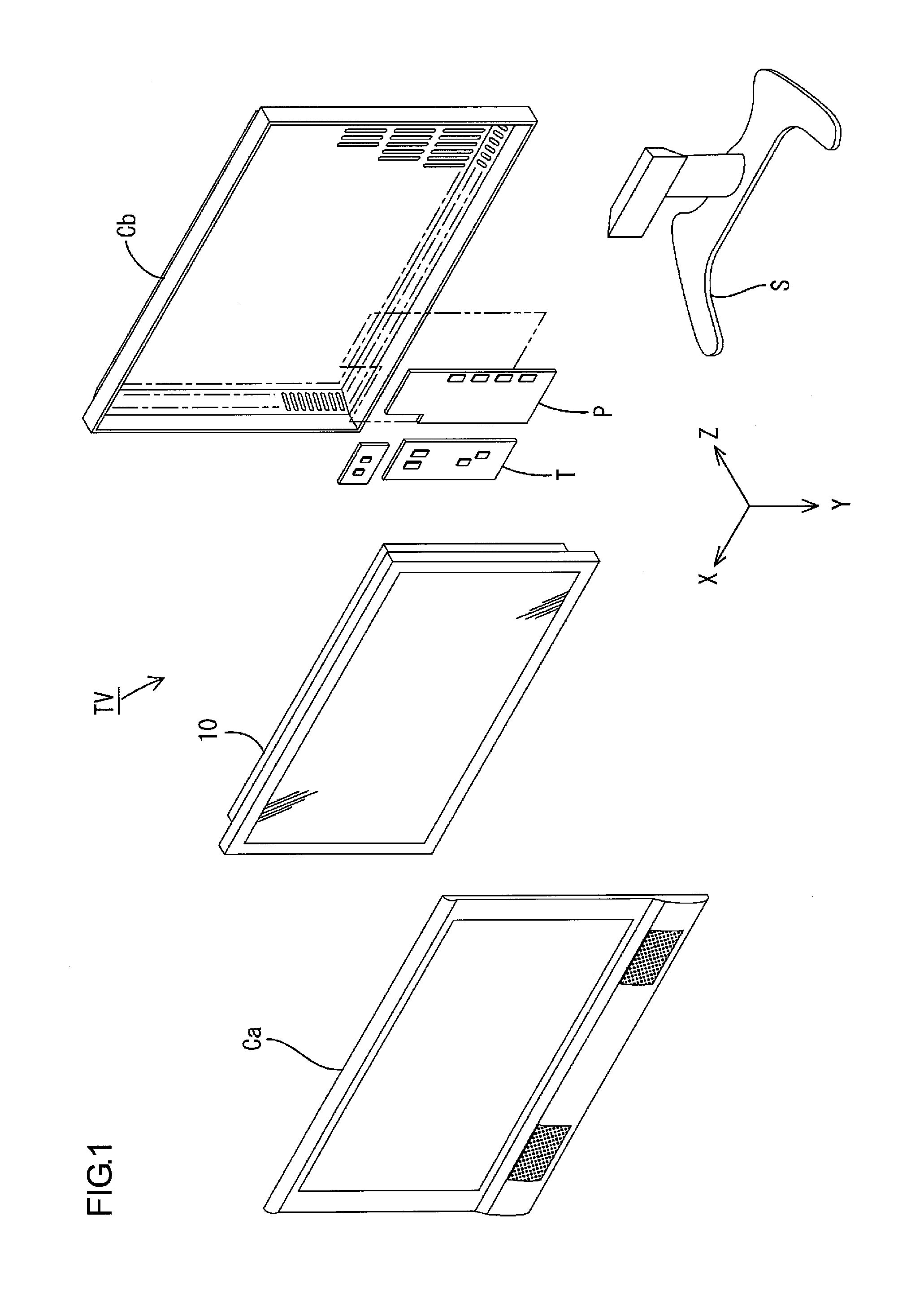
[0020]As illustrated in FIG. 1, the television receiver TV includes the liquid crystal display device 10 (a display device), a front cabinet Ca, a rear cabinet Cb, a power source P, and a tuner T. The cabinets Ca and Cb sandwich the liquid crystal display device 10 therebetween. The liquid crystal display device 10 is housed in the cabinets Ca and Cb. The liquid crystal display device 10 is held by a stand S in a vertical position in which a display surface 11a thereof is set along the vertical d...

second embodiment

[0056]Next, the second embodiment of the present invention will be explained with reference to FIGS. 7 and 8. In this embodiment, different guide mechanism components in support members 20A and a chassis 14A are used. Components similar to those of the first embodiment will be indicated with the same symbols followed by letter A. The same configuration, functions and effects will not be explained.

[0057]As illustrated in FIG. 7, each support member 20A has a crank-like shape in side view. It includes a main portion 21A and an extending portion 22A. The extending portion 22A projects from an end of the main portion 21A. The main portion 21A includes a pair of horizontal plates 21aA and 21bA along the Z-axis direction and a vertical plate 21cA along the Y-axis direction. The vertical plate 21c is connected to the ends of the horizontal plates 21a and 21b. The front horizontal plate 21aA is attached to a surface of the LED board 17a of the LED unit 17UA. The rear horizontal plate 21bA i...

third embodiment

[0060]Next, the third embodiment of the present invention will be explained with reference to FIGS. 9 and 10. In this embodiment, fixing points of a light guide plate 18B and the number of the follow-up mechanisms are different from other embodiments. Components similar to the first embodiment will be indicated with the same symbols followed by letter B. The same configuration, functions and effects will not be explained.

[0061]As illustrated in FIG. 9, a fixing pin 18dB projects from either short side surface of the light guide plate 18B around the center of the vertical dimension of the short side surface. A fixing hole 14eB for receiving the fixing pin 18dB is formed in either short side plate 14cB of a chassis 14B. When the light guide plate 18B thermally expands or contracts, the upper surface (including a light entrance surface 18bUB) of the light guide plate 18B and the bottom surface (including a light entrance surface 18bDB) move in the vertical direction. They move by subst...


PUM

PropertyMeasurementUnit
coefficient of thermal expansionaaaaaaaaaa
thicknessaaaaaaaaaa
temperatureaaaaaaaaaa

Abstract

A backlight unit 12 includes LED units 17, a light guide plate 18 and a follow-up mechanism. The light guide plate 18 has light entrance surfaces 18b and a light exit surface 18a. The light entrance surfaces 18b are provided so as to face the respective LED units 17. The light exit surface 18a is provided parallel to an arrangement direction in which the LED units 17 and the light entrance surface 18b are arranged (i.e., the Y-axis direction) and such that light exits therethrough. The follow-up mechanism is configured to move the LED unit 17U in the arrangement direction in response to a deformation of the light guide plate 18. The follow-up mechanism includes a support member 20 that supports the LED unit 17U. The support member is in contact with a surface of the light guide plate 18 along the light entrance surface 18bU.

Description

TECHNICAL FIELD[0001]The present invention relates to a lighting device, a display device and a television receiver.BACKGROUND ART[0002]In recent years, display components in image display devices including television receivers are being shifted from conventional cathode-ray tube display devices to thin display devices in which thin display components such as liquid crystal panels or plasma display panels are used. As a result, the image display devices are becoming thinner. Liquid crystal display devices require backlight units separately from liquid crystal panels because the liquid crystal panels do not emit light.[0003]A technology for reducing the thickness of liquid crystal display devices disclosed in Patent Document 1 is known. A backlight unit disclosed in the document includes LEDs and a light guide plate. Each LED has a light-emitting surface through which light is emitted in a direction substantially parallel to a display surface of a liquid crystal panel. The light guid...

Claims


Application Information

Patent Timeline
Patent Type & Authority Applications(United States)
IPC IPC(8): H04N3/14F21V8/00G02F1/13357F21V19/02
CPCG02B6/0068G02B6/0091G02F2001/133314G02F1/133615G02F1/133621G02F1/133308G02F1/133314
Inventor HAYASHI, KEIJI
Owner SHARP KK
Why Eureka
Try Eureka