

Telecommunications connections management
- Summary
- Abstract
- Description
- Claims
- Application Information
AI Technical Summary
Benefits of technology
Problems solved by technology
Method used
Image

Examples
Embodiment Construction
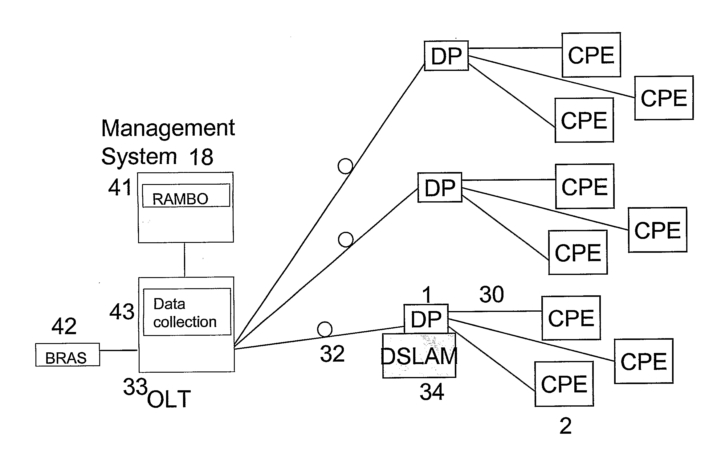
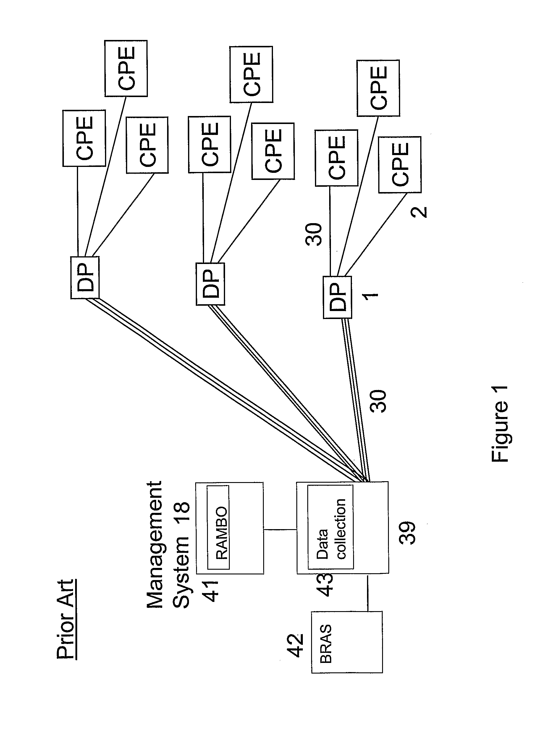
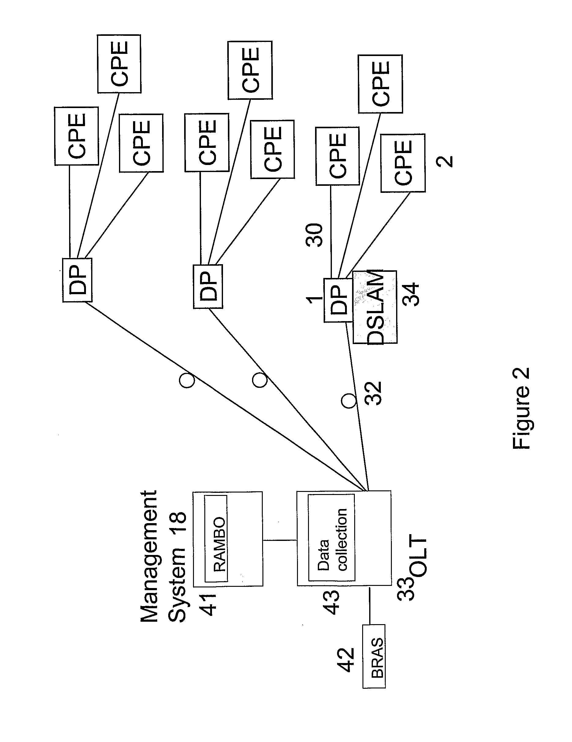
As shown in FIG. 1, in conventional Digital Subscriber Loop (DSL) services, provided from the exchange 39 (or cabinet), each customer premises 2 has a dedicated physical connection 30 to the DSL access multiplexer (DSLAM) 31 in the exchange 39. The connections from the exchange 39 to several different customer premises 2 may pass through a single distribution point 1, but each connection is a complete end-to-end connection.
A management system 18 can be provided to optimize the service for each customer by maximizing the data rate over the physical layer 30 (subject to a predetermined maximum) while maintaining the stability of the line. This is achieved for each line using a Dynamic Line Management (DLM) system and a Rate Adaptive Management Box (RAMBo) 41 which automatically selects the optimum rate profile for each line. The chosen profile rate (upstream and downstream) supported by the line is also applied to the BRAS (Broadband Remote Access Server) 42 serving the user connectio...
PUM
 Abstract
Description
Claims
Application Information