Cargo and vehicle inspection system

a technology for loading vehicles and moving sources, applied in the field of xray inspection technology, can solve the problems of substantial loss of time for both the operators of the inspection system and the drivers, low throughput of systems with moving sources and detectors of x-ray radiation, and low reliability

Active Publication Date: 2011-11-10
NAUCHNO PROIZVODSTVENNOE CHASTNOE UNITARNOE PREDPRIYATIE ADANI
View PDF6 Cites 51 Cited by
  • Summary
  • Abstract
  • Description
  • Claims
  • Application Information

AI Technical Summary

Benefits of technology

[0036]FIG. 9 shows the effect of a filter on the X-rays.

Problems solved by technology

Systems that have moving sources and detectors of X-ray radiation typically have fairly low throughput (measured in terms of number of vehicles per unit time), which is generally due to a relatively low scanning speed (typically in the range of 0.2-0.8 meters per second), as well as due to the need for the driver to leave the inspection area, or to at least stand sufficiently far from the radiation source (which results in substantial loss of time to both the operators of the inspection system and to the drivers); also, a relatively large area around the scanner needs to be reserved, due to the possible radiation exposure.
Also, such systems suffer from reliability problems due to the presence of moving parts, and require significant maintenance efforts.
Additionally, when both the source and the detector are in motion during the scan, the vibration effects cause fuzziness in the image, and lack of clarity.
However, the throughput of such scanning system tends to be fairly low, due to low scanning speed, and the need for the driver of the vehicle to leave the inspection area due to high radiation dosage use.
However, full radiation safety is still not achieved in this case, for example, for people who might be in the cargo hold of a truck, such as illegal immigrants, or for the driver's themselves, who are still exposed to at least some scattered radiation.
A heretofore unresolved problem however is forming an integrated system of monitoring a control that permits monitoring and detection of radioactive materials in automobiles and X-ray scanning and control from a single operations center.
In this case, the X-ray source and the collimator are located on a top bulkhead of the portal, which adds instability to the entire construction, while the X-ray detector is buried under the road.
Also, the described system uses a relatively low energy radiation source (140 KeV), which is only useful for X-ray monitoring of cars, which typically have metal body thickness of about 3 mm.
On the other hand, large automobiles, trucks, containers or container carriers typically cannot be scanned using the system, since they frequently have too much metal (often as much as 300 mm thick between the X-ray source and the detector), as well as due to the pressure exerted by the heavy vehicles on the road, which can affect the radiation detector buried under the road.

Method used


Image

  • Cargo and vehicle inspection system
  • Cargo and vehicle inspection system
  • Cargo and vehicle inspection system

Examples


Embodiment Construction

[0037]Reference will now be made in detail to the preferred embodiment of the present invention, examples of which are illustrated in the accompanying drawings.

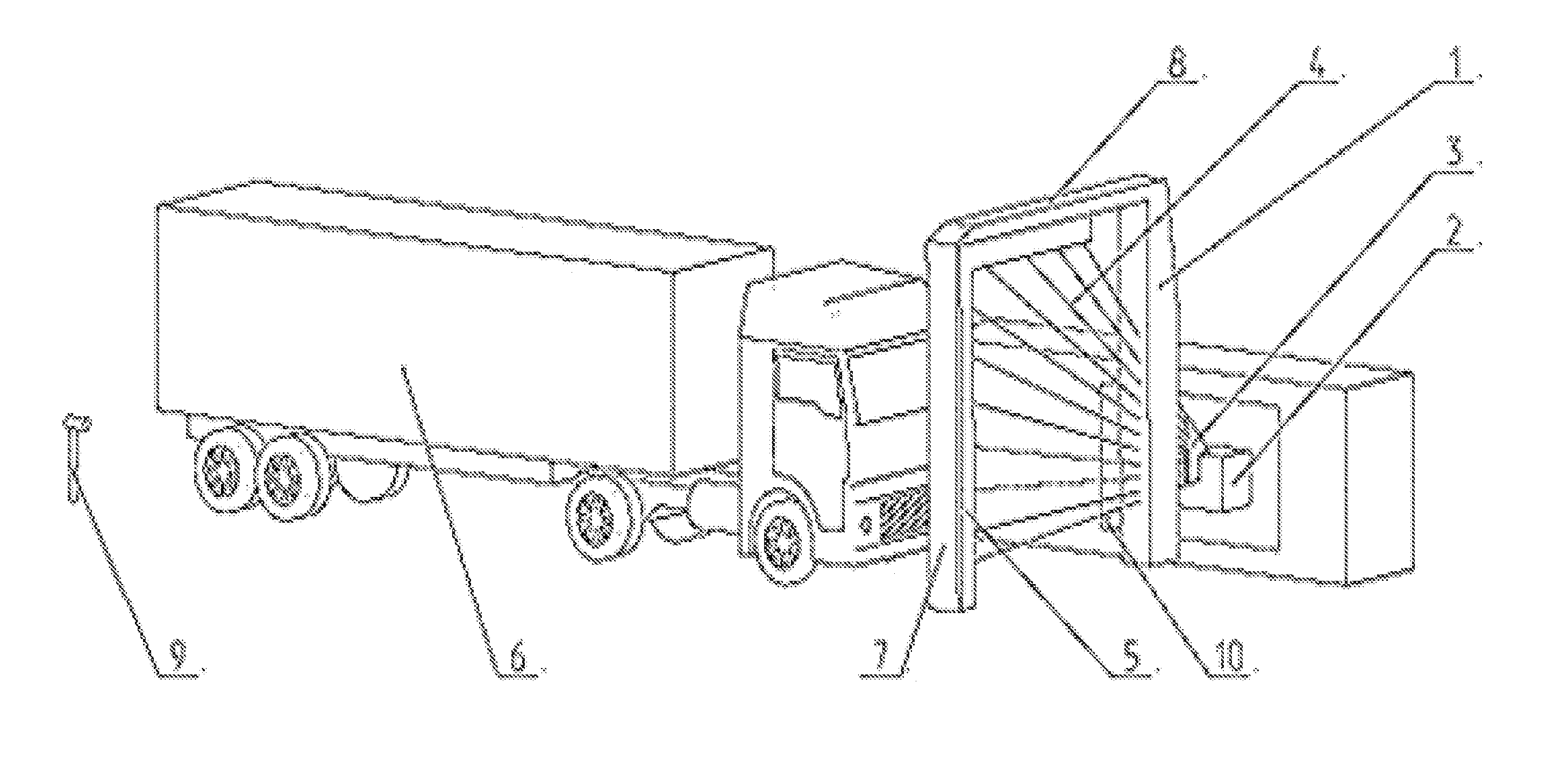
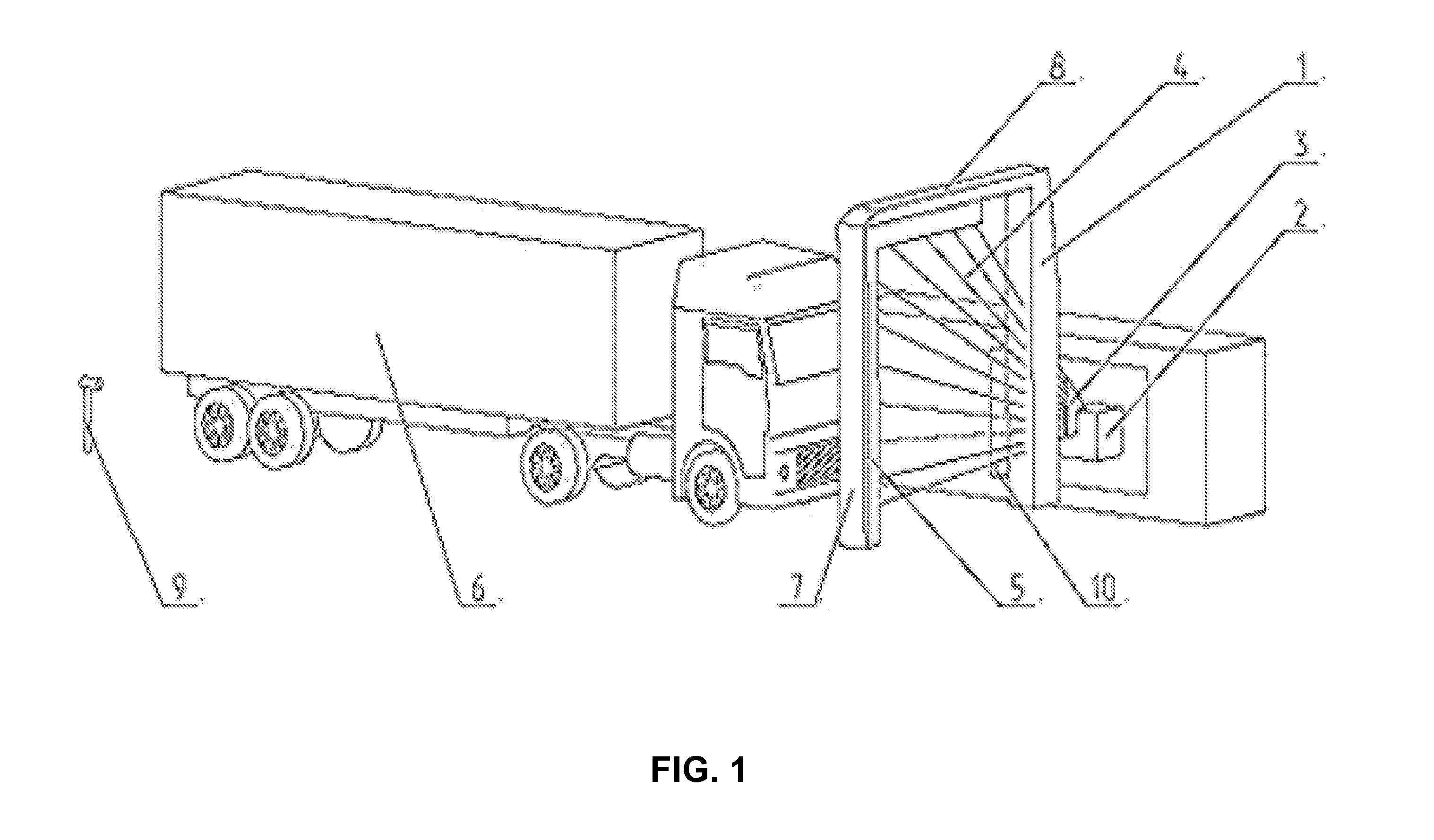
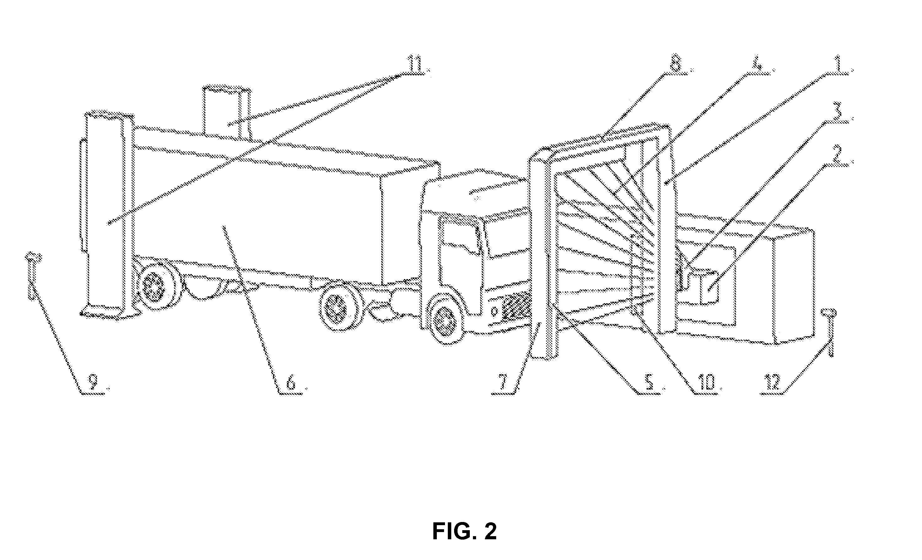
[0038]The apparatus for X-ray scanning of vehicles, according to the preferred embodiment, is shown in FIGS. 1, 2 and 3, and includes the portal 1, which has an X-ray radiation source 2 installed on one side. The X-ray source 2 includes a collimator 3, used for forming a fan-shaped X-ray beam 4. Opposite the source 2, a detector 5 is positioned, to receive the radiation passing through the vehicle, and to transform the received radiation into a digital electrical signal. In the illustrated example, the vehicle for which the radiation passes is designated by 6. In this example, the detector 5 is located on the vertical beam 7, and on the top horizontal beam 8 of the portal 1. A velocity measurement device 9 is also optionally included, to measure the speed of the vehicle 1. In the illustrated example, the velocity measurement ...


PUM

PropertyMeasurementUnit
energyaaaaaaaaaa
energyaaaaaaaaaa
energyaaaaaaaaaa

Abstract

An apparatus for X-ray scanning of vehicles includes a pulsed X-ray source generating X-rays. A collimator forms a fan-shaped beam from the X-rays. A detector detects the fan-shaped beam after it passes through a vehicle. A speed sensor measures a speed of the vehicle passing through the apparatus and providing an electrical output corresponding to the speed. An image formation module converts an output of the detector into an image of the vehicle, based on the measured speed of the vehicle. A cross-section of the fan-shaped beam is substantially similar to a width of the detector. The X-rays comprise primarily photons with energy between 2.5 and 9 MeV. A filter is adjacent to the collimator for filtering out low energy X-ray photons. A vehicle presence sensor can be used, whose output is used to turn the X-ray source on and off. An alignment platform can be used for aligning the fan-shaped beam with the detector. A frequency of the pulses is adjusted based on the speed of the vehicle. The X-ray source is turned off if the speed of the vehicle is below a predetermined threshold.

Description

CROSS-REFERENCE TO RELATED APPLICATIONS[0001]This application is a National Phase of PCT / BY2010 / 000003, filed on May 5, 2010 which is incorporated by reference herein in its entirety.BACKGROUND OF THE INVENTION[0002]1. Field of the Invention[0003]The present invention is directed to X-ray inspection technology, and more particularly, to a system and method for high-energy X-ray inspection of loaded vehicles (container or general cargo), and more particularly, to effective screening cargo at critical facilities, seaports and border crossing.[0004]2. Description of the Related Art[0005]Many systems for radiation inspection of trucks and containers are known, most of which are, generally, based on the same principle, general of X-ray radiation by and X-ray source, forming, using a collimator, a fan-shaped X-ray beam directed at the vehicle, scanning the vehicle using the fan-shaped beam, and converting the detected radiation, after it passes through the vehicle, into a digital signal, ...

Claims


Application Information

Patent Timeline
Patent Type & Authority Applications(United States)
IPC IPC(8): G01N23/04
CPCG01V5/005G01V5/0033
Inventor LINEV, VLADIMIR N.
Owner NAUCHNO PROIZVODSTVENNOE CHASTNOE UNITARNOE PREDPRIYATIE ADANI
Why Eureka
Try Eureka