
Measurement of blood flow dynamics with x-ray computed tomography: dynamic ct angiography

a technology of computed tomography and x-ray, applied in tomography, angiography, instruments, etc., can solve the problems of ambiguity regarding the functional relevance, misinterpretation of the severity of arterial stenoses, and little to no information provided by cta regarding the physiology of blood flow in a subj

Active Publication Date: 2011-11-10
RGT UNIV OF CALIFORNIA
View PDF4 Cites 45 Cited by
  • Summary
  • Abstract
  • Description
  • Claims
  • Application Information

AI Technical Summary

Benefits of technology

The patent describes a method for using data collected from medical imaging devices to determine blood flow dynamics, such as velocity, volume, and pressure. This is done by analyzing raw CT data to compute three-dimensional images of an area of interest. The method can provide real-time or offline information associated with blood flow dynamics, which can be used for diagnostics and treatment purposes. The technique involves determining a contrast concentration at each of a plurality of projection angles, which is then compared across one or more rows of a multi-row CT scanner to determine blood flow dynamics. The method can generate information associated with blood flow dynamics in a subject, which can be displayed on a display device. The patent also provides various systems and apparatuses for measuring blood flow dynamics.

Problems solved by technology

However, one limitation of CTA is that CTA provides little to no information regarding the physiology of blood flow in a subject, such as flow velocity and turbulence.
The absence of such blood flow data can lead to ambiguity regarding the functional relevance of the morphological findings provided by CTA.
Furthermore, such ambiguity may result in a misinterpretation of the severity of arterial stenoses.
Other available imaging methods that allow for blood flow assessments can also be limited because these methods either impose a relatively high risk of injury to the patient (e.g., conventional invasive catheter angiography) or are simply limited in scope (e.g., ultrasound).
Furthermore, data obtained from exams that provide anatomical information can be difficult to combine with data obtain from exams that provide physiological information.

Method used


Image

  • Measurement of blood flow dynamics with x-ray computed tomography: dynamic ct angiography
  • Measurement of blood flow dynamics with x-ray computed tomography: dynamic ct angiography
  • Measurement of blood flow dynamics with x-ray computed tomography: dynamic ct angiography

Examples


Embodiment Construction

Angiography is generally used as a medical test to help physicians or other medical and clinical personnel diagnose and treat medical conditions related to blood vessels. Angiography may use one or more imaging technologies to produce images of blood vessels. In some cases, a contrast material may be injected into a subject in order to produce pictures of blood vessels throughout the body. Angiography may be performed using X-rays with invasive catheters, or using more non-invasive techniques, such as computed tomography (CT), magnetic resonance imaging (MRI), or the like. In general, an ideal imaging method for vascular evaluation would be noninvasive, well tolerated, fast, and deliver excellent anatomical and physiological information about the blood vessels.

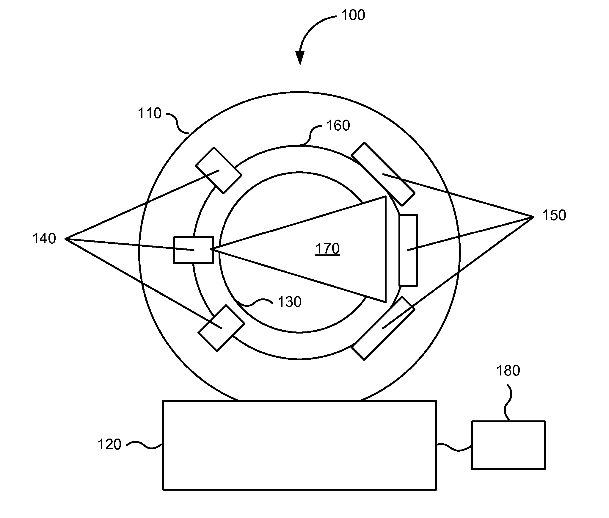
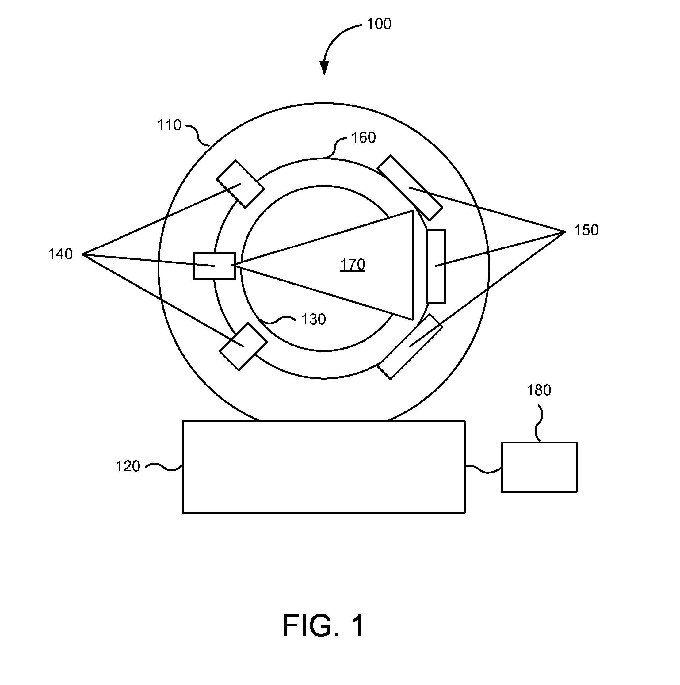
FIG. 1 is an illustration of medical imaging device 100 that may be used in various embodiments according to the present invention for the measurement of blood flow dynamics.

In general, medical imaging device 100 can include a...


PUM


Abstract

In various embodiments, systems and methods can provide accurate measurements of blood flow dynamics in a subject. Projection data acquired during a computed tomography (CT) scan of the subject can be used to determine information representing inflow of a contrast material. Accordingly, a measurement of flow velocity, in addition to other aspects of flow, may be obtained from the projection data.

Description

BACKGROUND OF THE INVENTIONArterial disease can be considered one of the leading causes of mortality and morbidity in the United States, responsible for every third death or 2,500 deaths per day in the U.S. alone. Arterial disease may claims more lives each year than cancer, chronic lower respiratory diseases, accidents, and diabetes mellitus combined. As a result, clinical angiographic imaging (CAI) to diagnose vascular disease has increased by approximately 23% over the past 5 years. CAI may now be performed for approximately 1% of all Medicare patients.Computed-Tomography Angiography (CTA) is one noninvasive imaging modality for evaluation of blood vessels and may be steadily replacing conventional invasive catheter-based angiography as the first-line diagnostic test for the evaluation of arterial disease. CTA can virtually replace all other alternative imaging modalities for some indications. CTA offers many advantages for the evaluation of arterial disease, including ease of us...

Claims


Application Information

Patent Timeline
Patent Type & Authority Applications(United States)
IPC IPC(8): G06K9/00
CPCG06T11/005G06T2211/404A61B6/504A61B6/032A61B6/481G06T2211/412
Inventor PREVRHAL, SVENRINKEL, JEANFORSYTHE, CARLOSYEH, BENJAMIN M.
Owner RGT UNIV OF CALIFORNIA
Learn More