

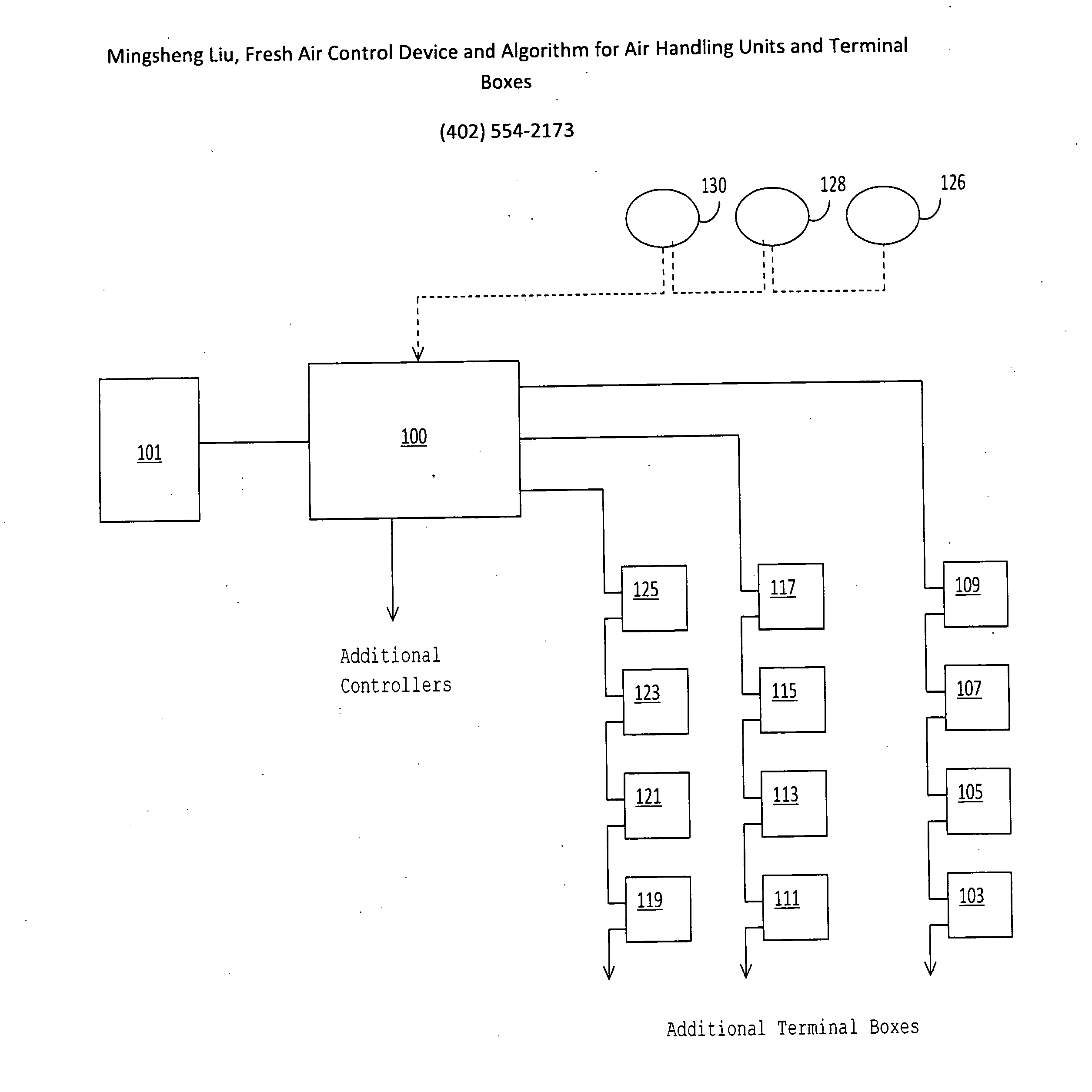
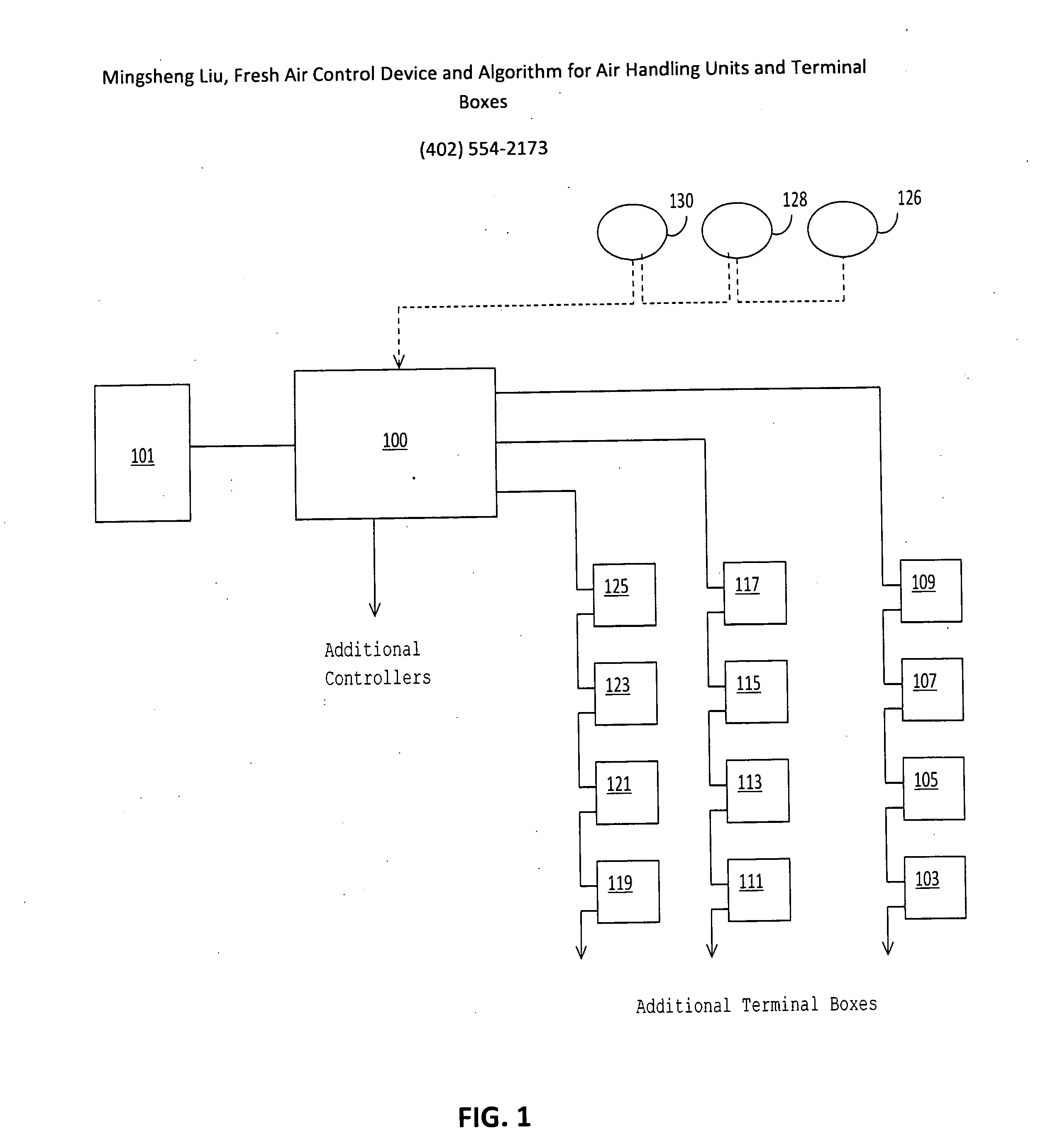
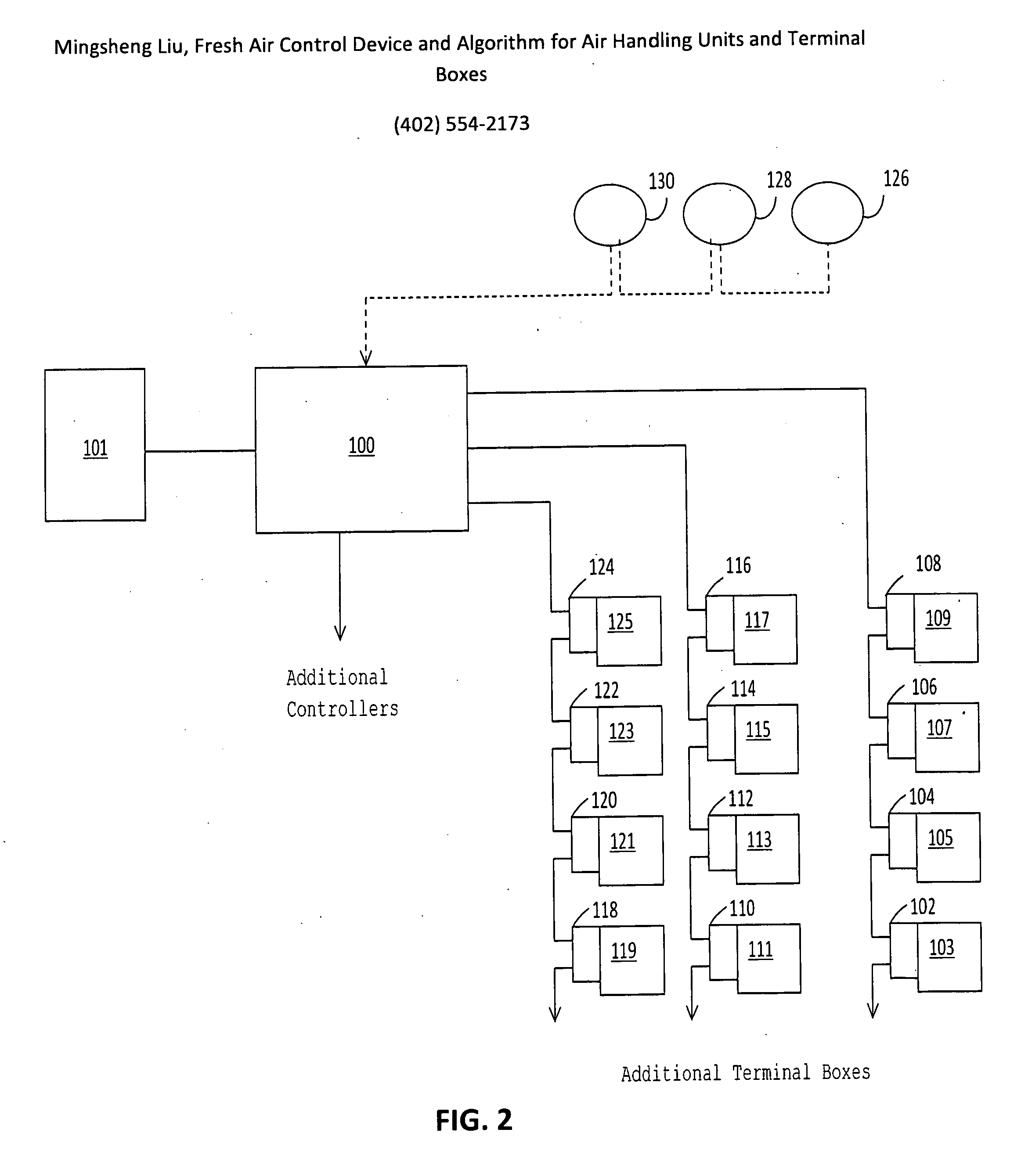
Fresh air control device and algorithm for air handling units and terminal boxes
a control device and terminal box technology, applied in the field of air handling units, can solve the problems of not meeting the fresh air requirement in every zone, unable to apply a method, and significant consumption of heating, cooling and fan power energy
- Summary
- Abstract
- Description
- Claims
- Application Information
AI Technical Summary
Benefits of technology
Problems solved by technology
Method used
Image

Examples
Embodiment Construction
[0027]Before any embodiments of the invention are explained in detail, it is to be understood that the invention is not limited in its application to the details of construction and the arrangement of components set forth in the following description or illustrated in the following drawings. The invention is capable of other embodiments and of being practiced or of being carried out in various ways. Also, it is to be understood that the phraseology and terminology used herein is for the purpose of description and should not be regarded as limiting. The use of “including,”“comprising,” and variations thereof herein is meant to encompass the items listed thereafter and equivalents thereof as well as additional items. Unless specified or limited otherwise, the terms “attached,”“connected,”“supported,” and variations thereof are used broadly and encompass both direct and indirect mountings, connections, and supports. Further, “connected” is not restricted to physical or mechanical conne...
PUM
 Abstract
Description
Claims
Application Information