Cross Controller Clock Synchronization

a cross-controller and clock synchronization technology, applied in multiplex communication, generating/distributing signals, instruments, etc., can solve problems such as compounding problems, easy to combine triggers, and inability to combine triggers at all, and achieve accurate control of data acquisition

a cross-controller and clock synchronization technology, applied in multiplex communication, generating/distributing signals, instruments, etc., can solve problems such as compounding problems, easy to combine triggers, and inability to combine triggers at all, and achieve accurate control of data acquisition

US20110276820A1Active Publication Date: 2011-11-10NATIONAL INSTRUMENTS

Image

  • Cross Controller Clock Synchronization
  • Cross Controller Clock Synchronization
  • Cross Controller Clock Synchronization

Examples


Embodiment Construction

[0023]In the following description, numerous specific details are set forth to provide a thorough understanding of various embodiments. However, one of ordinary skill in the art will recognize that these specific details are included for illustrative purposes to provide a better understanding of the overriding principles common to many different possible embodiments. Accordingly, other embodiments featuring details that may differ from the specific details provided herein may perform similar functions to achieve similar goals as the disclosed embodiments, and other embodiments may thus be derived from the specific details and embodiments disclosed herein. In some instances, well-known circuits, structures, and techniques have not been shown in detail to avoid obscuring the novelty of the overriding principles.

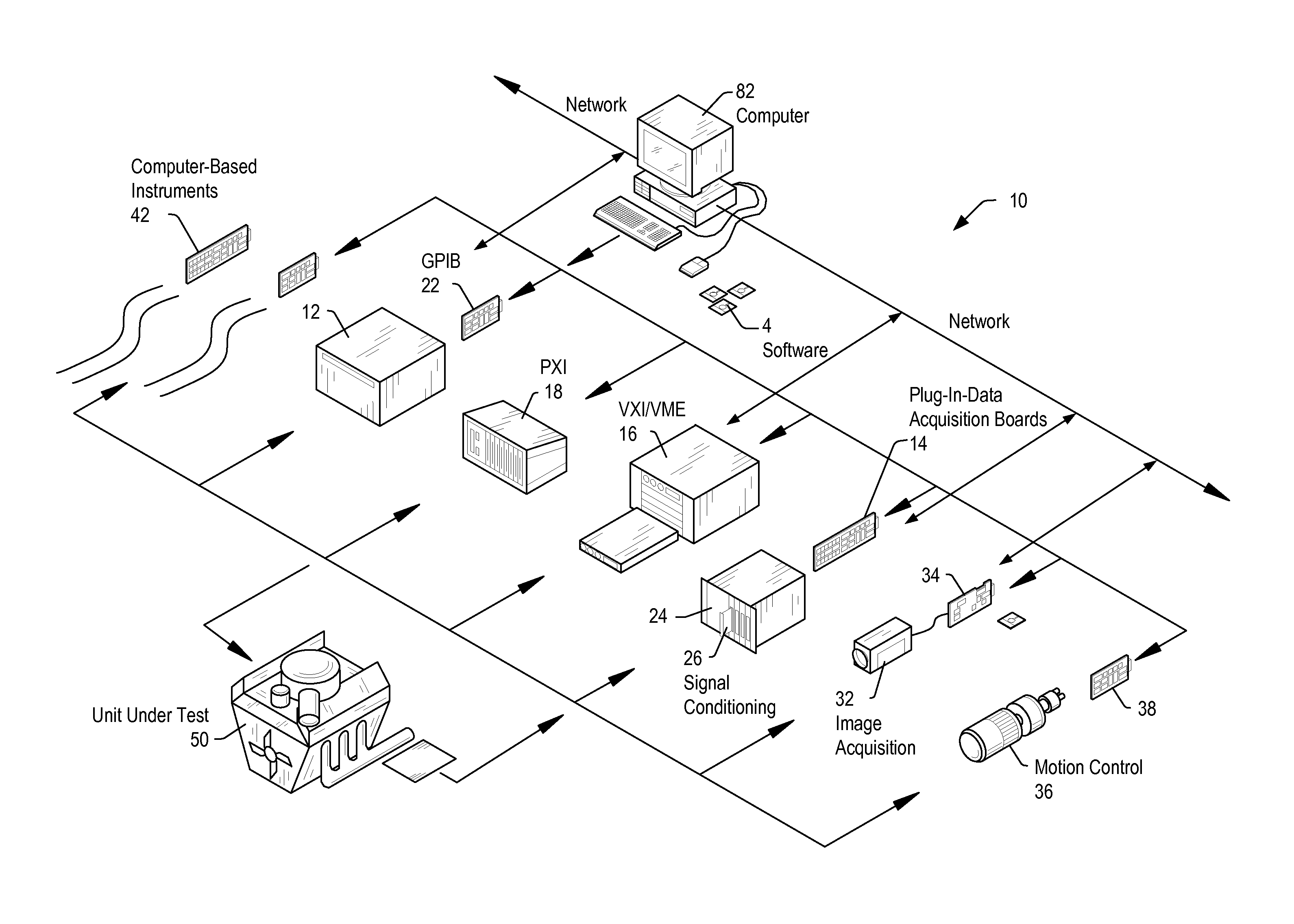
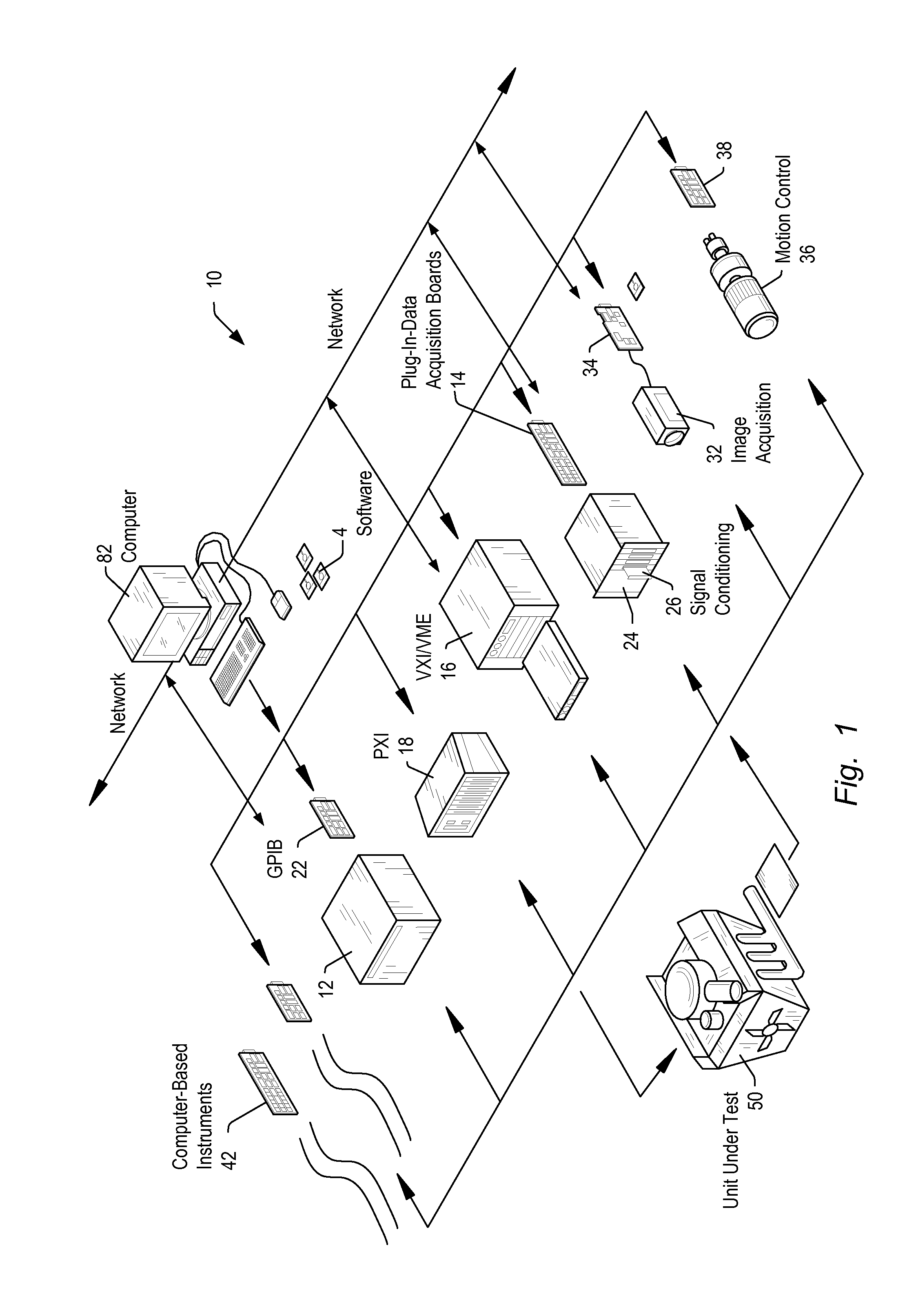
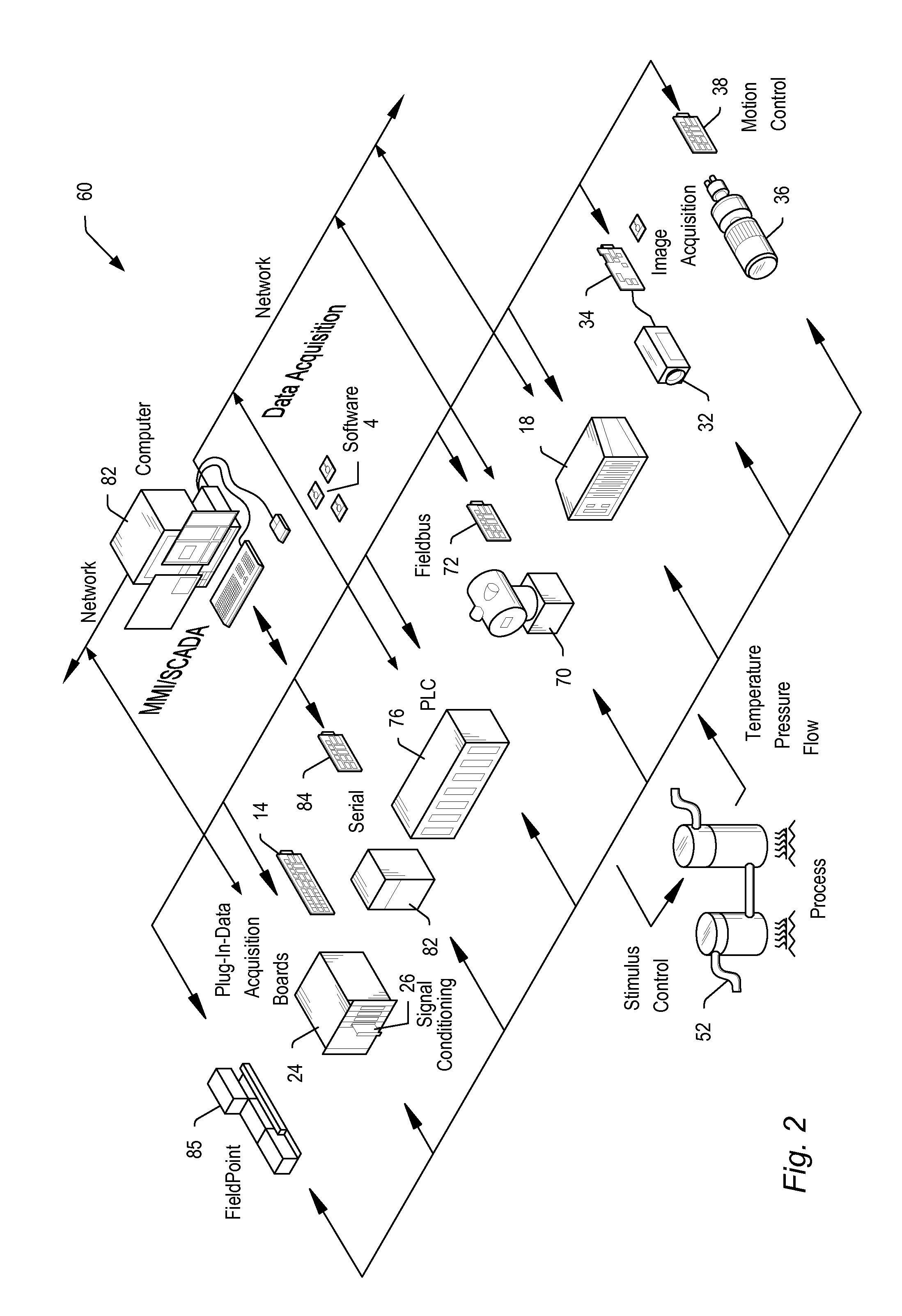
[0024]Embodiments of the present invention may be used in systems configured to perform test and / or measurement functions, to control and / or model instrumentation or industrial...


PUM


Abstract

A system may include a plurality of subsystems, e.g. instrumentation units housed in separate chassis, each chassis including multiple instrumentation devices, e.g. data acquisition cards. Each subsystem may generate a local reference clock, which may be phase aligned and locked with respect to one or more similar reference clocks of other subsystems, via a high-level precision time protocol (PTP). Each instrumentation device within a given subsystem may generate its own sample clock based on the local reference clock, and may generate its own trigger clock based on its own sample clock. All trigger clocks may be synchronized with respect to each other through a future time event issued using the PTP, and each instrumentation device may then use its trigger clock to synchronize any received trigger pulses, which may also be issued through future time events using the PTP. This results in synchronizing the received triggers across all participating instrumentation devices across all participating subsystems, ensuring that data acquisition is properly synchronized across the multiple subsystems.

Description

FIELD OF THE INVENTION[0001]This invention relates to signal synchronization, and more specifically to synchronizing timing measurements across multiple systems.DESCRIPTION OF THE RELATED ART[0002]In many industrial applications (and others), instruments collect data or information from an environment or unit under test (UUT), and may also analyze and process acquired data. Some instruments provide test stimuli to a UUT. Examples of instruments include oscilloscopes, digital multimeters, pressure sensors, arbitrary waveform generators, digital waveform generators, etc. The information that may be collected by respective instruments includes information describing voltage, resistance, distance, velocity, pressure, oscillation frequency, humidity, and / or temperature, among others. Computer-based instrumentation systems typically include transducers for capturing a physical phenomenon and generating a representative electrical signal, signal conditioning logic to perform amplification ...

Claims


Application Information

Patent Timeline
10 Nov 2011
Publication
US20110276820A1
IPC
G06F1/12; G06F1/04
CPC
G06F1/12; H04L7/0008; H04J3/0667
Inventors
PATEL, KUNAL H.; ULLRICH, ADAM C.