Apparatus for and method of manufacturing a helically wound tubular structure

a technology of helically wound tubular structure and manufacturing method, which is applied in the direction of metal rolling, material accumulation devices, transportation and packaging, etc., can solve the problems of complex process and long process, and achieve the effect of facilitating continuous supply of strip material and reducing downtim

Inactive Publication Date: 2011-11-17
ITI SCOTLAND
View PDF4 Cites 5 Cited by
  • Summary
  • Abstract
  • Description
  • Claims
  • Application Information

AI Technical Summary

Benefits of technology

[0005]It is an object of the present invention to provide an apparatus for and method of manufacturing tubular structures which reduces and possibly overcomes some of the problems associated with the prior art.
[0007]Advantageously, this arrangement permits the outer and inner portions of the stock of material to be rotated at different speeds, facilitating the controlled consumption of stock at the forming station. Additionally, variation of angular speeds of different elements in the arrangement permits a reduction or even elimination of downtime for reloading of stock, by continuing consumption during the reloading. This allows for greater uniformity of the manufactured helical winding.
[0010]According to another aspect of the invention loading may be performed with minimal interruption or without interruption of the inner winding process, by which strip material taken from the inner portion of the stock is wound on to a central core or mandrel. This reduces downtime and may facilitate continuous supply of the strip material toward to the core, so that the final helical winding is uniform along the length of the manufactured pipe.

Problems solved by technology

This is a complex process.
This can be a very lengthy process.

Method used


Image

  • Apparatus for and method of manufacturing a helically wound tubular structure
  • Apparatus for and method of manufacturing a helically wound tubular structure
  • Apparatus for and method of manufacturing a helically wound tubular structure

Examples


Embodiment Construction

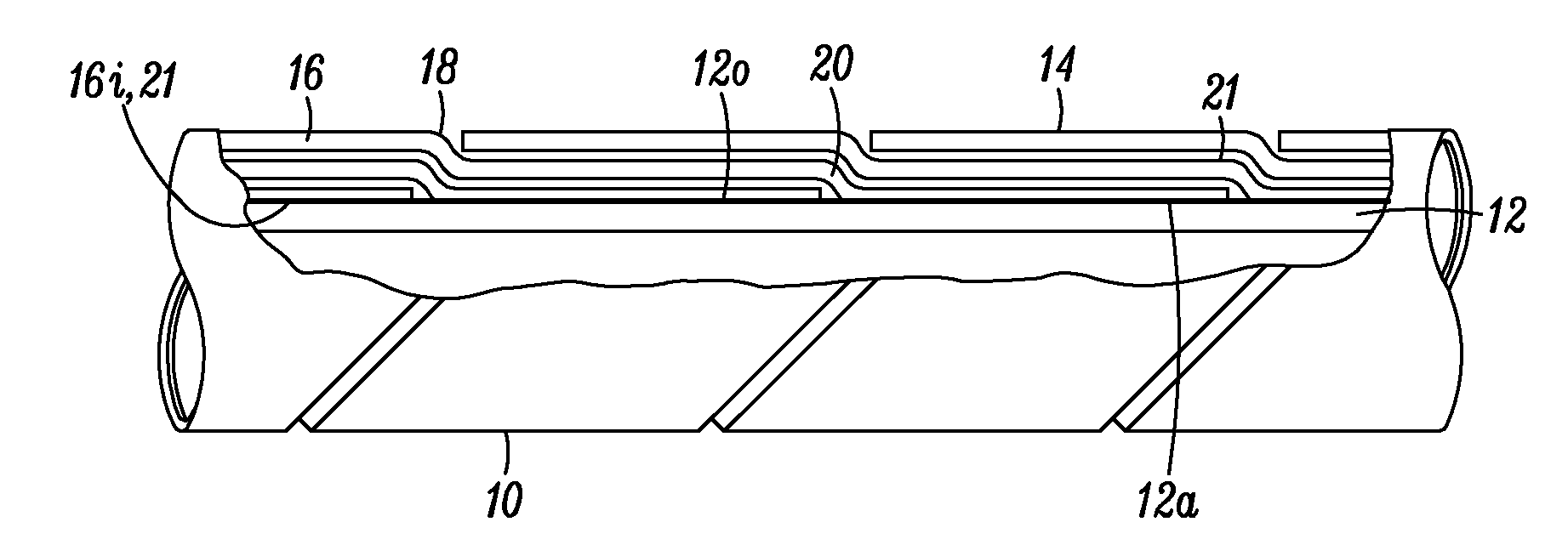
[0018]Referring now to FIG. 1 of the drawings, a tubular body indicated generally at 10 forms a pipe for use in a pipe system such as a pipeline carrying hot fluids (which may also be under pressure). The tubular body may comprise an inner portion in the form of an inner hollow core 12 which may be formed by any one of a number of forming processes known to those skilled in the art and an outer load carrying casing discussed in detail later herein. In the preferred process the inner pipe comprises a continuously formed core, as will also be discussed in detail later herein however, one may have a core made from a plurality of discrete lengths inter-engaged with each other so as to form a long length. The outer casing indicated generally at 14 is formed on the inner hollow core 12 by helically winding a strip 16 of material onto the outer surface 12a of the core 12 in an abutting or self-overlapping fashion similar to the manner which is described in detail for the formation of a pip...


PUM

PropertyMeasurementUnit
distanceaaaaaaaaaa
rotationaaaaaaaaaa
outer diameteraaaaaaaaaa

Abstract

An apparatus (50) for and method of manufacturing structures (116) includes coaxial rotating faceplates (74, 89, 97), capable of rotation at different angular speeds. A plurality of forming rollers (76) and diameter defining rollers (78) are mounted on the inner faceplate (74, 89), which, in operation, cause a strip material (80) to be plastically deformed into a helical winding which may be lain down in abutting or self-overlapping relationship to form said tubular structure (116). A plurality of support rollers are mounted in a circle on the inner faceplate (74, 89) at a distance from the axis exceeding that of the outermost forming roller and serve to support the stock of strip material.

Description

CROSS-REFERENCE TO RELATED APPLICATIONS[0001]This application is a United States national phase application under 35 U.S.C. §371 of International Patent Application No. PCT / GB2010 / 050054 filed on Jan. 14, 2010, and claims the benefit of Great Britain Patent Application No. 0900721.2 filed on Jan. 16, 2009, both of which are herein incorporated in their entirety by reference. The International Application was published as International Publication No. WO 2010 / 082058 on Jul. 22, 2010.FIELD[0002]The present invention relates to a winding apparatus and a method of manufacturing structures and relates particularly to the manufacture of pipes and longitudinal structures formed by winding strips of material, such as metal, Kevlar, plastic, glass fibre, composites of such materials or strips formed from layers comprising one or more of said materials in a helical relationship. Other structures such as storage vessels, towers and support structures may also benefit from features described he...

Claims


Application Information

Patent Timeline
Patent Type & Authority Applications(United States)
IPC IPC(8): B21B1/08B21C37/06
CPCB21C37/121B21C37/126B21C37/128B21C49/00B65H2701/173B29C53/8016B65H20/26B65H2301/414321B65H2403/725B29C53/68B21C37/12
Inventor CURTIS, RICHARD MARTIN
Owner ITI SCOTLAND
Why Eureka
Try Eureka