Method for calibrating an acceleration sensor and electronic device

Inactive Publication Date: 2011-11-17
ROBERT BOSCH GMBH
View PDF2 Cites 19 Cited by
  • Summary
  • Abstract
  • Description
  • Claims
  • Application Information

AI Technical Summary

Benefits of technology

[0006]The method and the electronic device according to the present invention have the advantage over the related art that the presence of a resting state is detectable in a comparatively simple, energy-saving and efficient manner and therefore, a calibration of the acceleration sensor is only carried out in the presence of such a resting state. In the spirit of the present invention, a resting state (also denoted here as a “1 g” state) is, in particular, a state in which, in essence, only gravitational force (“1 g” acceleration, “g” standing for the acceleration due to gravity) is acting as an acceleration force and no “free fall” is present. For example, the portable device in which the acceleration sensor to be calibrated is situated lies stationary on a support surface such as a granite table plate. This has the advantage that the calibration of the acceleration sensor is carried out exclusively in the resting state and, in particular, not during the presence of other dominating acceleration forces, since a precise measurement of acceleration due to gravity is only possible in this case. In this context, the acceleration sensor is adjusted or calibrated, in particular, in light of the measurement of the known acceleration due to gravity. Therefore, both a calibration of an already pre-calibrated acceleration sensor and a calibration of a still uncalibrated acceleration sensor are rendered possible in an advantageous manner. This allows, for example, (post- and/or re-) calibration of the acceleration sensor during the use of a device in which the acceleration sensor is integr

Problems solved by technology

However, this method is not suitable for calibrating acceleration sensors in portable devices by measuring gravitational acceleration in a resting state, i.e., a “1 g” state of the portable device, since in this case, in addition to the detection of the resting state (dete

Method used


Image

  • Method for calibrating an acceleration sensor and electronic device
  • Method for calibrating an acceleration sensor and electronic device
  • Method for calibrating an acceleration sensor and electronic device

Examples


Embodiment Construction

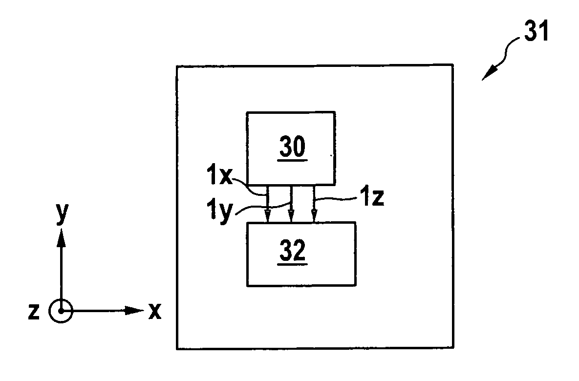
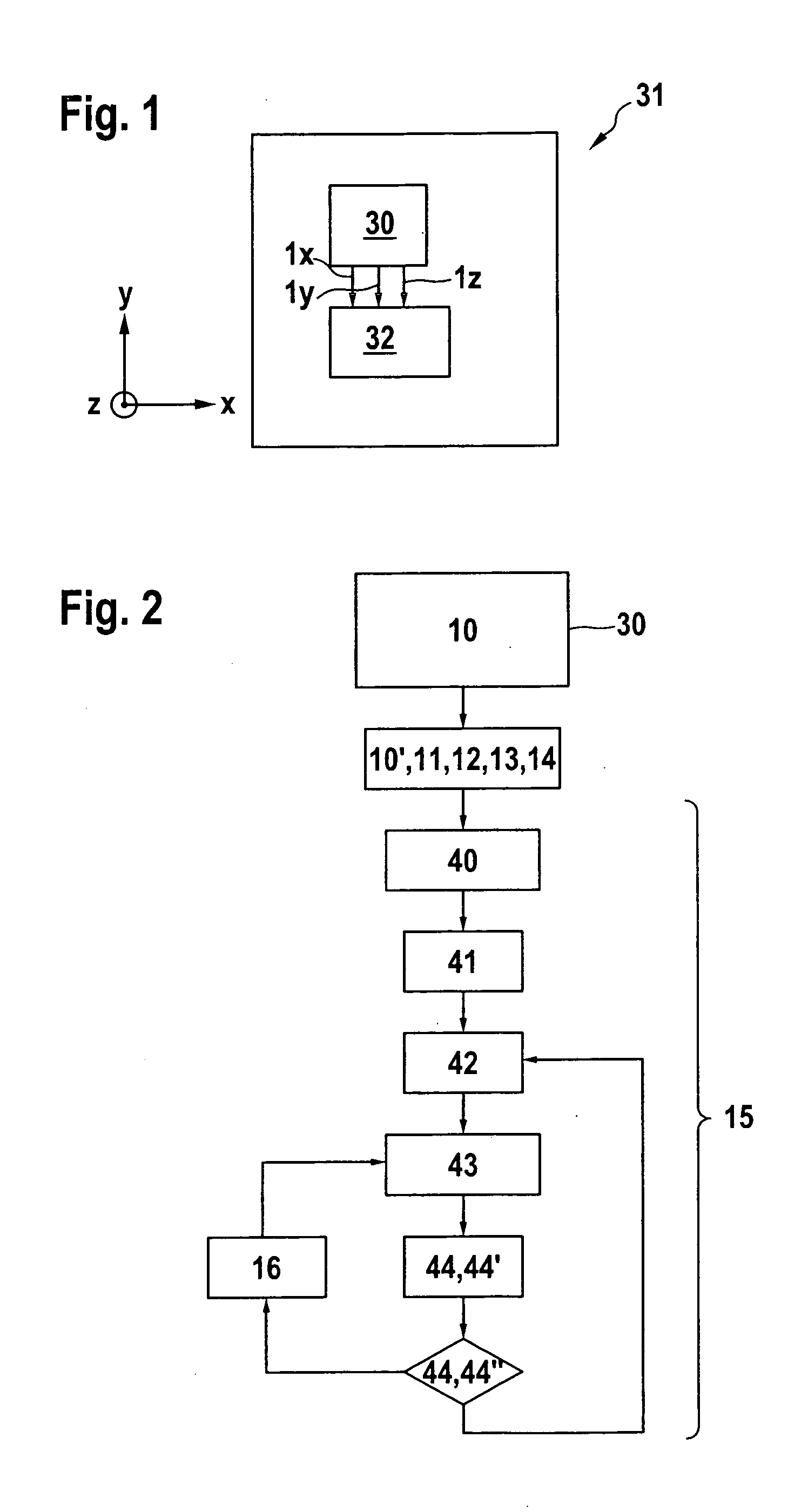
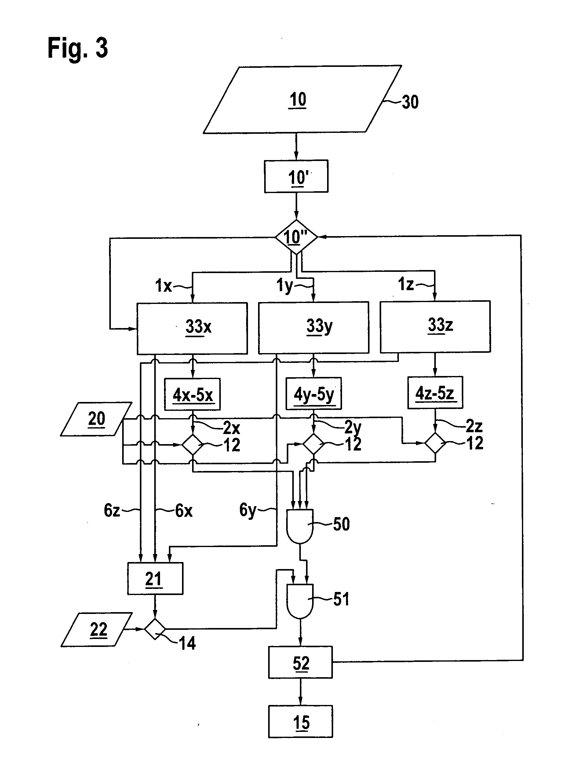
[0018]FIG. 1 shows a schematic view of an electronic device 31, which has an acceleration sensor 30, and in which a method for calibrating acceleration sensor 30 according to a first exemplary embodiment of the present invention is executed. Electronic device 31 includes, in particular, a mobile, portable device, such as a cellular phone. Electronic device 31 has the at least one acceleration sensor 30, as well as an evaluation unit 32. Acceleration sensor 30 includes a micromechanical, three-channel acceleration sensor, which is sensitive with respect to all three spatial directions X, Y, Z, i.e., measures accelerations along each of the three spatial directions X, Y, Z. The accelerations measured along each of the three spatial directions X, Y, Z are transmitted, in the form of acceleration values 1X, 1Y, 1Z and sorted according to respective spatial direction X, Y, Z, to evaluation unit 32. With the aid of these acceleration values 1X, 1Y, 1Z, evaluation unit 32 detects if electr...


PUM


Abstract

A method for calibrating an acceleration sensor includes the following sequential steps: ascertaining acceleration values as a function of three spatial directions; for each of the three spatial directions, generating a comparison value from the acceleration values; comparing each of the comparison values to a first threshold value; calculating a cumulative value as a function of at least one acceleration value for each of the three spatial directions; comparing the cumulative value to a second threshold value; and calibrating the acceleration sensor when, in the third method step, for each of the three spatial directions, the comparison value is less than the threshold value, and when, in the fifth method step, the cumulative value is greater than the further threshold value.

Description

BACKGROUND OF THE INVENTION[0001]1. Field of the Invention[0002]The present invention relates to a method for calibrating an acceleration sensor.[0003]2. Field of the Invention[0004]Methods of this kind are generally known. For example, printed German patent application document DE 10 2007 002 835 A1 describes a method for calibrating a yaw rate sensor system, in which calibration is carried out using inclination data from an acceleration sensor system. The acceleration sensor system also sends a calibration-initiating zero signal to the yaw-rate sensor system as soon as a resting state is detected, so that in each instance, the calibration of the yaw-rate sensor system is only carried out in the resting states.[0005]However, this method is not suitable for calibrating acceleration sensors in portable devices by measuring gravitational acceleration in a resting state, i.e., a “1 g” state of the portable device, since in this case, in addition to the detection of the resting state (d...

Claims


Application Information

Patent Timeline
IPC IPC(8): G01P21/00G01P15/18
CPCG01P21/00G01P15/18G01P15/00
Inventor BARTHOLOMEYCZIK, JULIANSCHEIERMANN, SERGEJ
Owner ROBERT BOSCH GMBH
Why Eureka
Try Eureka