Shock Absorbing System For Energy Recycling

a technology of energy recycling and shock absorption, which is applied in the direction of machines/engines, mechanical equipment, etc., can solve the problems of reducing the life of batteries, failure to retrieve energy, and unstable electrical curren

Active Publication Date: 2011-11-17
NAT TAIWAN UNIV
View PDF10 Cites 45 Cited by
  • Summary
  • Abstract
  • Description
  • Claims
  • Application Information

AI Technical Summary

Problems solved by technology

However, the mentioned electric generating apparatus is only capable to retrieve the energy sourced during the compressing phase of the spring, but fails to retrieve the energy during the expanding period of the spring.
However, the rotations of the rotor are unstable since the reciprocating movements of the wheel are essentially a random-based motion, which causes the electrical current unstable and reduces the life for the battery.
However, the issues regarding the low efficiency of energy retrieving and unstable electrical current are urged to be resolved or improved.

Method used


Image

  • Shock Absorbing System For Energy Recycling
  • Shock Absorbing System For Energy Recycling
  • Shock Absorbing System For Energy Recycling

Examples


Embodiment Construction

[0031]The present invention will now be described more specifically to the following embodiments. However, it is to be noted that the following descriptions of preferred embodiments of this invention are presented herein for the purposes of illustration and description only; it is not intended to be exhaustive or to be limited to the precise form disclosed.

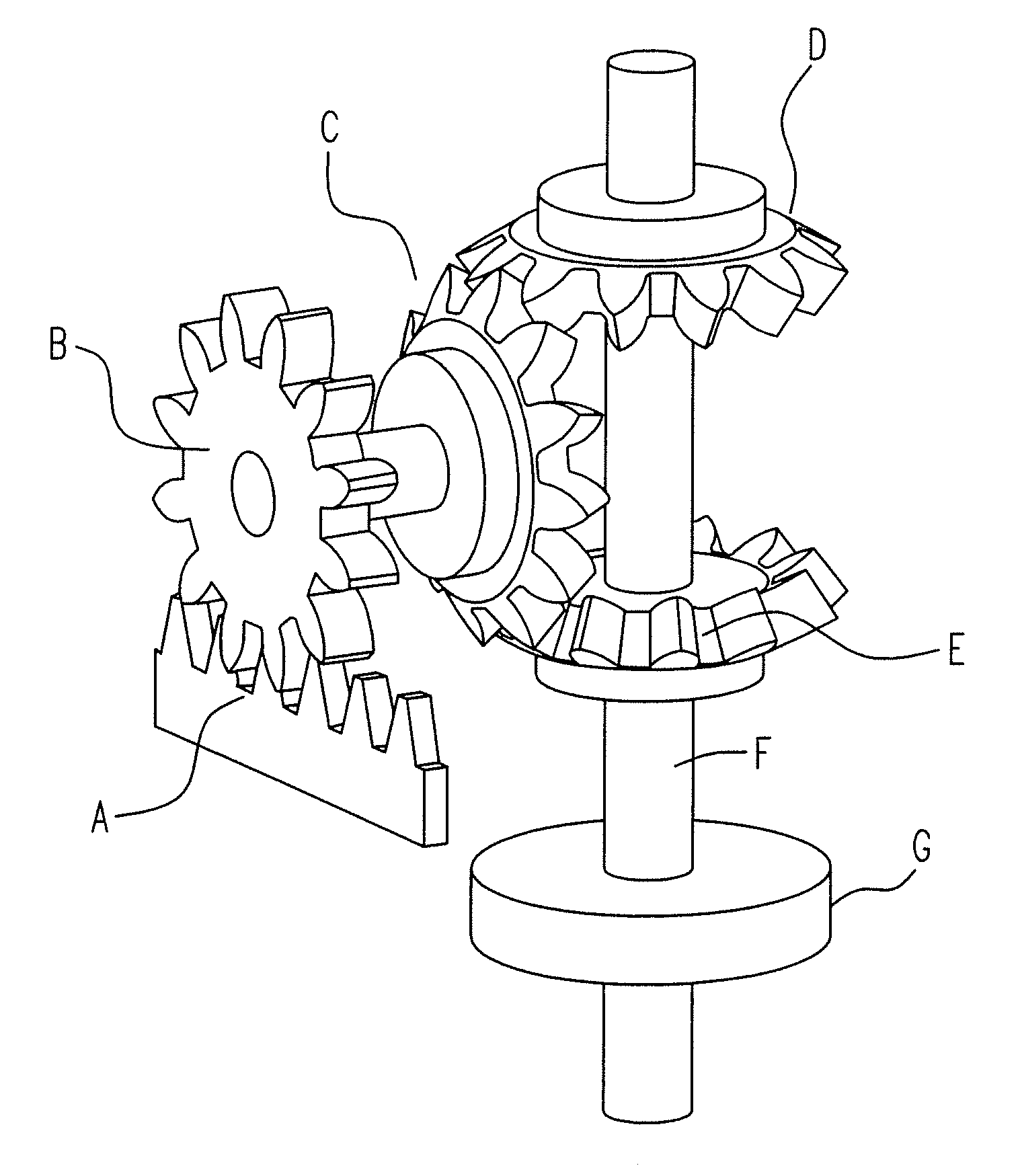
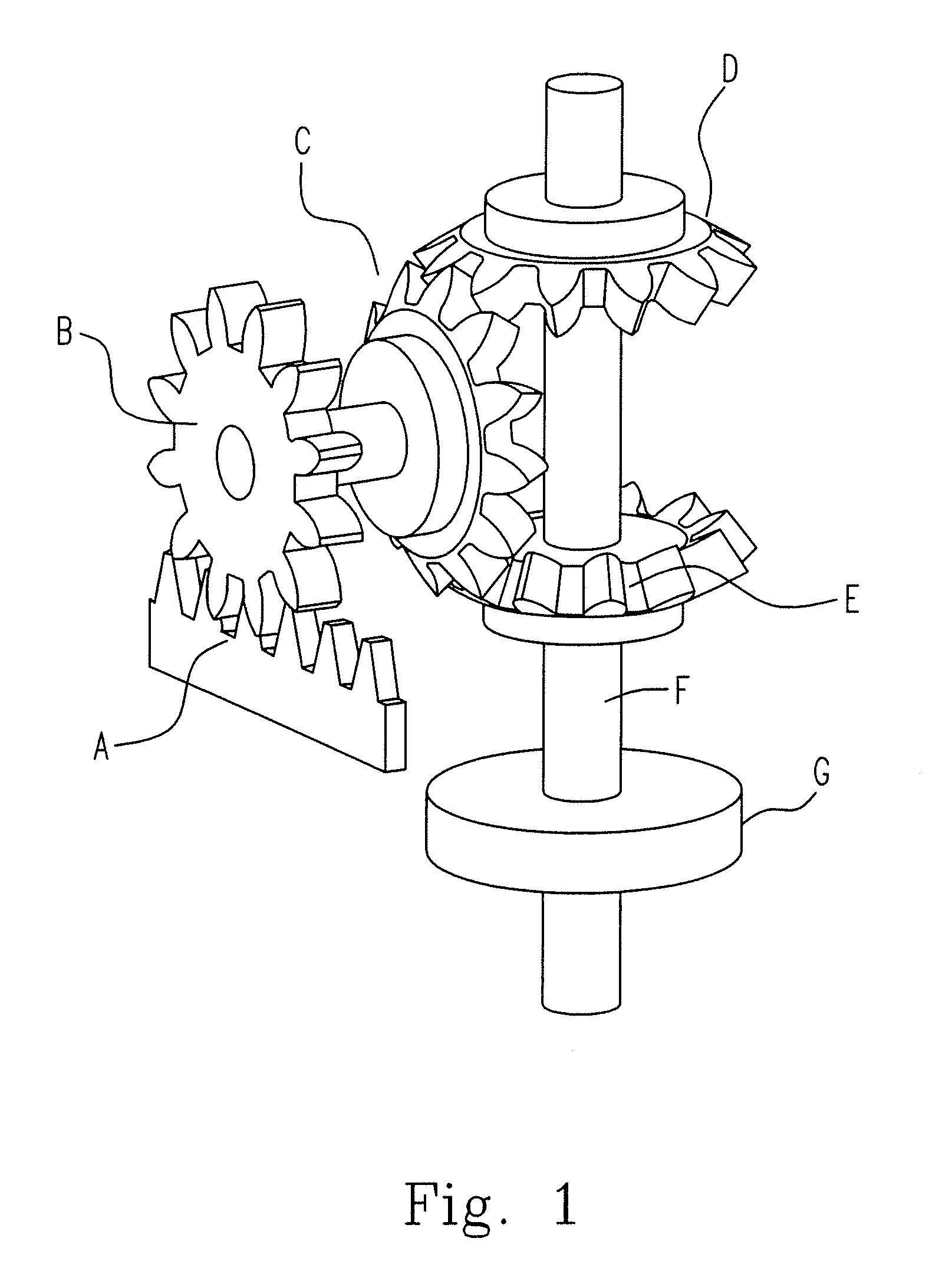
[0032]Please refer to FIG. 1, which is a diagram illustrating the first embodiment for the gear set according to the present invention. In FIG. 1, the gear rack A is engaged with the spur gear B. Since the spur gear B and the bevel gear C are coaxially disposed on the same shaft, the bevel gear C will be driven by the spur gear B when the spur gear B is revolved. The bevel gear C is engage with the first non-return gear D and the second non-return gear E respectively. Since the first non-return gear D and the second non-return gear E are coaxially disposed on the same shaft F and each of the first non-return gear D and the second ...


PUM


Abstract

A shock absorber is provided in the present invention. The shock absorber includes a resilient element; a gear set comprising a first non-return gear and a second non-return gear; and an electric generator driven by the first non-return gear to generate a power when the resilient element is compressed and driven by the second non-return gear when the resilient element is loosened.

Description

FIELD OF THE INVENTION[0001]The invention is related to a shock absorbing system, and more particularly to a dual-direction shock absorbing system for retrieving mechanical energy sourced from displacements of elastic element therein and transforming it into electric energy.BACKGROUND OF THE INVENTION[0002]There is usually a shock absorber disposed in a vibrating absorber or a damper that is installed in vehicles, transportations or buildings, for absorbing / dissipating the kinematic energy resulted from vibrations or quakes and maintaining safety and comfort for people on / in the vehicles, transportations or buildings. A shock absorber typically consists of mechanical viscous dampers and elastic elements. The state of the art already provides abundant techniques that well utilize the kinematic energy sourced from the compressions and relaxations of the spring or the elastic elements.[0003]For instances, the Taiwan Utility Model Pat. No. M284604 discloses an electric generating appara...

Claims


Application Information

Patent Timeline
Patent Type & Authority Applications(United States)
IPC IPC(8): F03G7/08H02K7/116
CPCF03G7/08Y10T74/18128H02K7/1853F16F15/04
Inventor JIANG, JOE-AIRSU, WEI-SHENGYANG, YU-CHENGCHUANG, CHENG-LONGLIN, TZU-SHIANG
Owner NAT TAIWAN UNIV
Why Eureka
Try Eureka