Stator for electric rotating machine

a technology of electric rotating machines and stators, which is applied in the direction of dynamo-electric machines, electrical apparatus, windings, etc., can solve the problems of increasing the size of stators b>10/b> undesirably, and the mountability of electric rotating machines in automotive vehicles deterioration, so as to increase the cost of materials

Active Publication Date: 2011-11-17
DENSO CORP
View PDF2 Cites 20 Cited by
  • Summary
  • Abstract
  • Description
  • Claims
  • Application Information

AI Technical Summary

Benefits of technology

[0011]It is therefore an object to provide an improved structure of a stator of an electric rotating machine designed to ensure a required degree of electrical insulation between coil ends of conductor segments to be welded without needs for increasing the cost of material of a stator winding and entire size of the stator.
[0014]Specifically, at least one of the heads of the conductor segments in the radial array is interposed between adjacent two of the coil end pairs, thereby ensuring a distance between the adjacent two of the coil end pairs which is great enough to provide a required degree of electric insulation between the coil end pairs when the ends of the conductor segments are welded electrically.
[0015]The above layout of the coil end pairs of the conductor segments eliminates the need for the ends of the conductor segments to have the length required to bend base portions thereof outward in the radial direction of the stator core, thus permitting the overall height of the ends of the conductor segments to be decreased. This also permits the stator to be downsized in the axial direction thereof, which improves the mountability of the electric rotating machine in the automotive vehicles.

Problems solved by technology

Such radial in-line arrangement of the coil ends 16b may result in a lack of an interval d1 between every adjacent two of the coil ends 16b required to ensure the electric insulation therebetween, which may result in undesirable electrical discharge when the coil ends 16b are welded.
This leads to an increase in size of the stator 10 undesirably.
The increased size of the stator 10 requires increasing the size of a motor housing in which the stator 10 is to be disposed, which will result in deterioration in mountability of the electric rotating machine in automotive vehicles.
Each of the conductor segments 16b is also required to have a length great enough to bent the base portion 16e both in the outward direction and in the circumferential direction of the stator core 14, thus resulting in an increase in material cost of the stator winding 16.

Method used


Image

  • Stator for electric rotating machine
  • Stator for electric rotating machine
  • Stator for electric rotating machine

Examples


Embodiment Construction

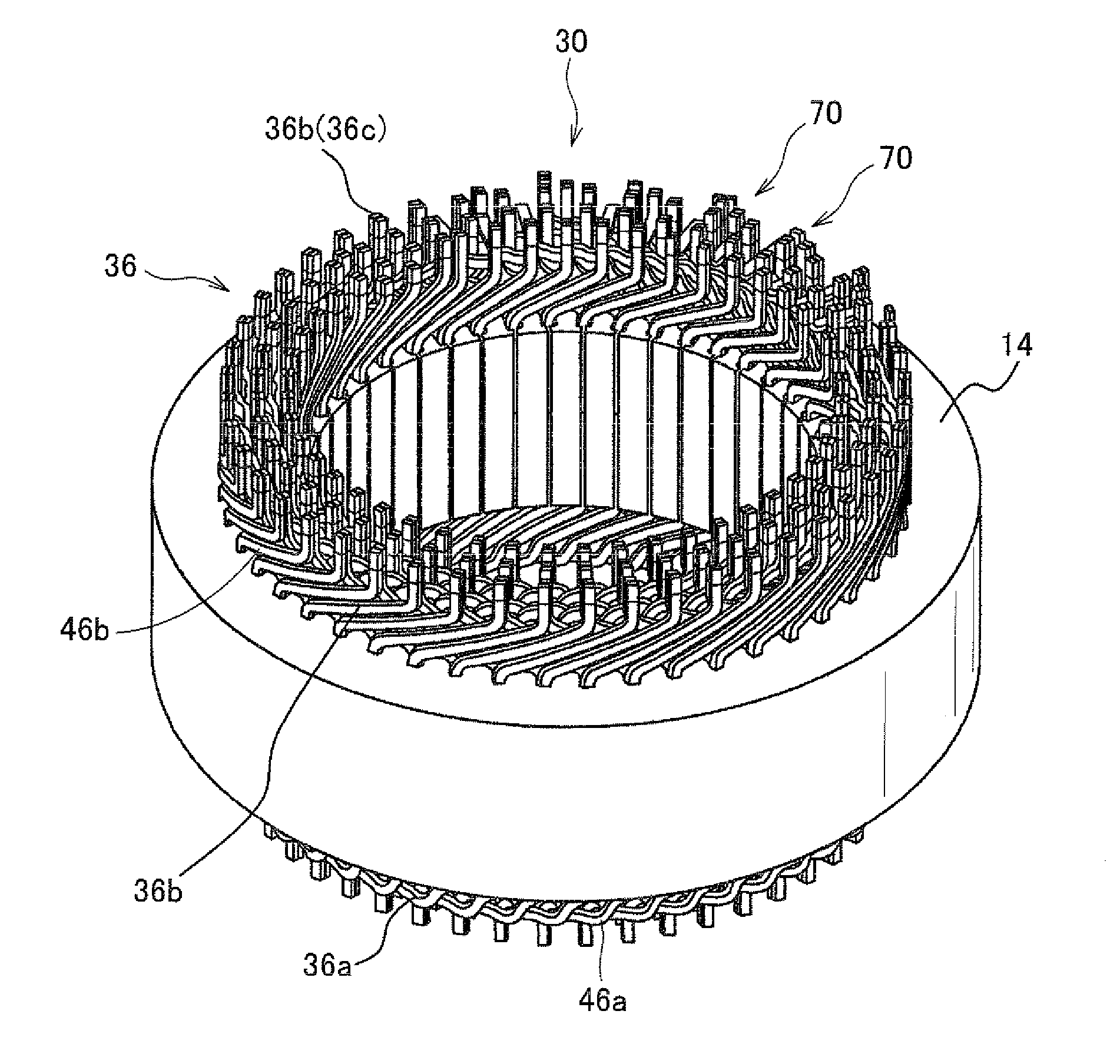
[0039]Referring to the drawings, wherein like reference numbers refer to like parts in several views, particularly to FIGS. 7 and 8, there is shown a stator 30 of an electric rotating machine such as an electric motor, an electric generator, or a motor-generator. FIG. 7 is a perspective view of the stator 30, as viewed from the side where electric leads extending from three-phase windings of an inverter (not shown) are connected to the stator 30 (which will also be referred to as a lead side below). FIG. 8 is a perspective view of the stator 30, as viewed from the opposite side of the lead side (which will also be referred to as an opposite lead side below).

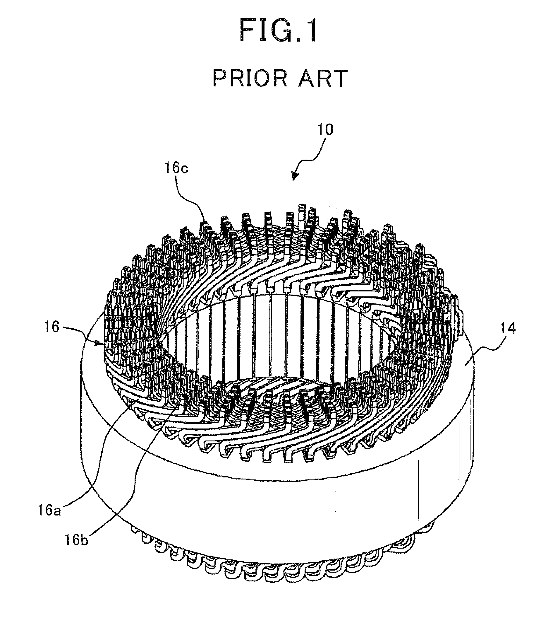
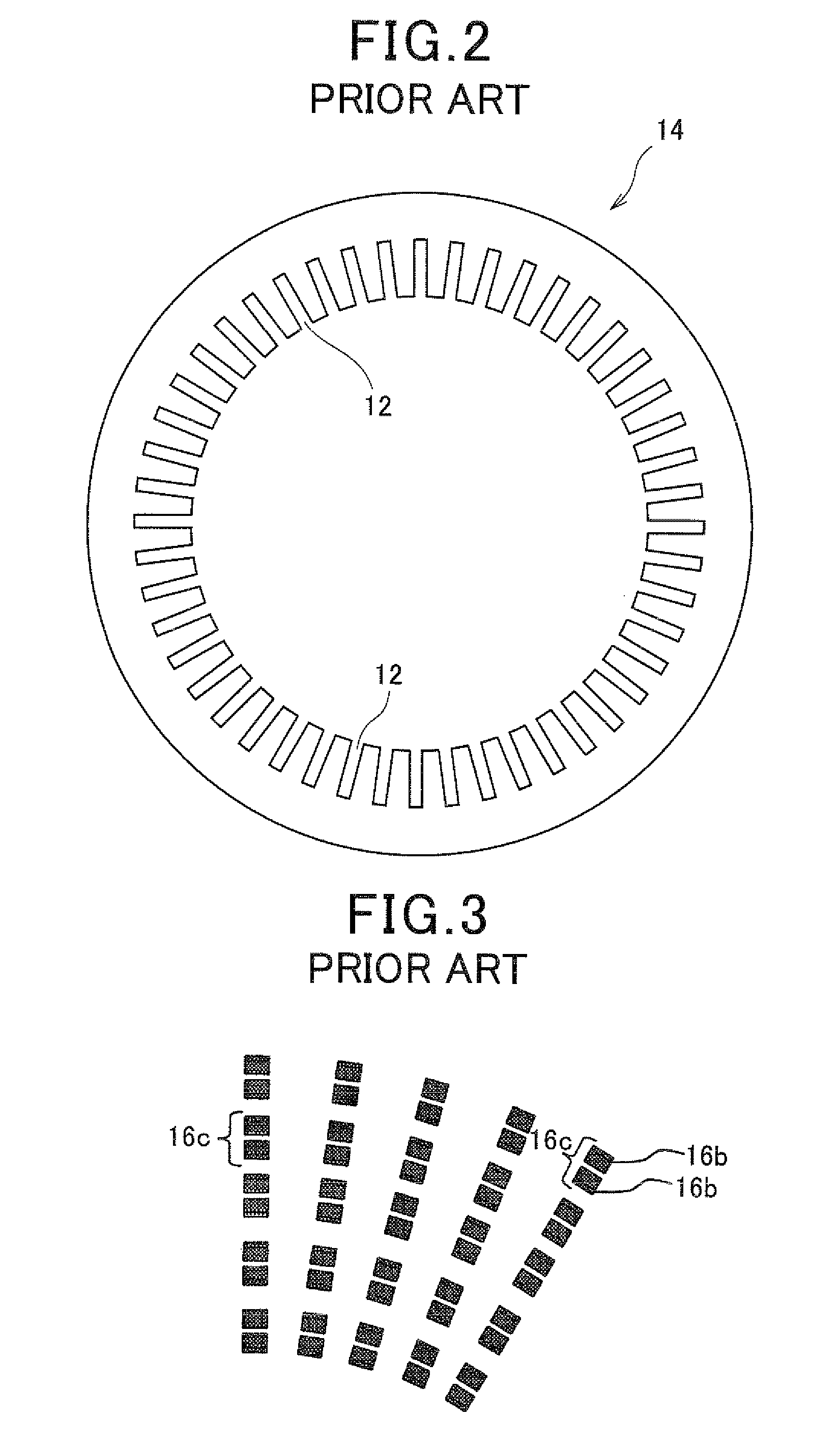
[0040]The stator 30 includes an annular stator core 14 and a multi-phase stator winding 36. The stator core 14 is substantially identical in structure with the one of FIG. 2 and has a plurality of slots 12 formed in an inner periphery thereof. The slots 12 are arrayed at regular intervals in a circumferential direction of the sta...


PUM

PropertyMeasurementUnit
shapeaaaaaaaaaa
electricaaaaaaaaaa
anglesaaaaaaaaaa

Abstract

A stator for an electric rotating machine is equipped with a stator winding made up of a plurality of conductor segments. Each of the conductor segments has a head and two legs. The legs are inserted through their respective slots formed in a stator core, so that each of the conductor segments has leg ends protruding from either one of opposed end surfaces of the stator core and the head thereof protruding from the other end surface. Radially adjacent two of the leg ends are provided as a coil end pair to be welded. At least one of the heads is interposed between adjacent two of the coil end pairs, thereby ensuring a distance between the two adjacent coil end pairs which is great enough to provide a required degree of electric insulation between the coil end pairs when the leg ends of the conductor segments are welded electrically.

Description

CROSS REFERENCE TO RELATED DOCUMENT[0001]The present application claims the benefit of priority of Japanese Patent Application No. 2010-111443 filed on May 13, 2010, the disclosure of which is incorporated herein by reference.BACKGROUND OF THE INVENTION[0002]1. Technical Field[0003]The present invention relates generally to a stator of an electric rotating machine such as an electric motor or an electric generator to be mounted in, for example, automotive vehicles such as electric vehicles or hybrid vehicles and a production method thereof.[0004]2. Background Art[0005]FIG. 1 illustrates a conventional stator 10 for use in electric rotating machines. The stator 10 includes an annular stator core 14 and a stator winding 16. The stator core 14, as illustrated in FIG. 2, has a plurality of slots 12 arrayed at regular intervals in a circumferential direction thereof. The stator winding 16 is wound through the slots 12 of the stator core 14. The stator winding 16 is made up of a plurality...

Claims


Application Information

Patent Timeline
Patent Type & Authority Applications(United States)
IPC IPC(8): H02K3/28H02K15/00
CPCH02K3/12Y10T29/49009H02K3/28
Inventor UTAKA, RYOSUKEHISADA, TOMOKAZU
Owner DENSO CORP
Why Eureka
Try Eureka