Vibration wave actuator

a vibration wave actuator and actuator technology, applied in the direction of generator/motor, television system, instruments, etc., can solve problems such as unsolved, and achieve the effects of improving pressure contact force, pressure stabilization, and reducing pressure application structur

Inactive Publication Date: 2011-11-17
CANON KK
View PDF9 Cites 12 Cited by
  • Summary
  • Abstract
  • Description
  • Claims
  • Application Information

AI Technical Summary

Benefits of technology

[0021]The present invention enables provision of a vibration wave actuator, which is a vibratory drive apparatus that enhances a pressure-contact force provided by magnetism between a vibrator and a driven element, enabling stabilization of a state of the...

Problems solved by technology

However, in the conventional vibratory drive a...

Method used


Image

  • Vibration wave actuator
  • Vibration wave actuator
  • Vibration wave actuator

Examples


embodiment 1

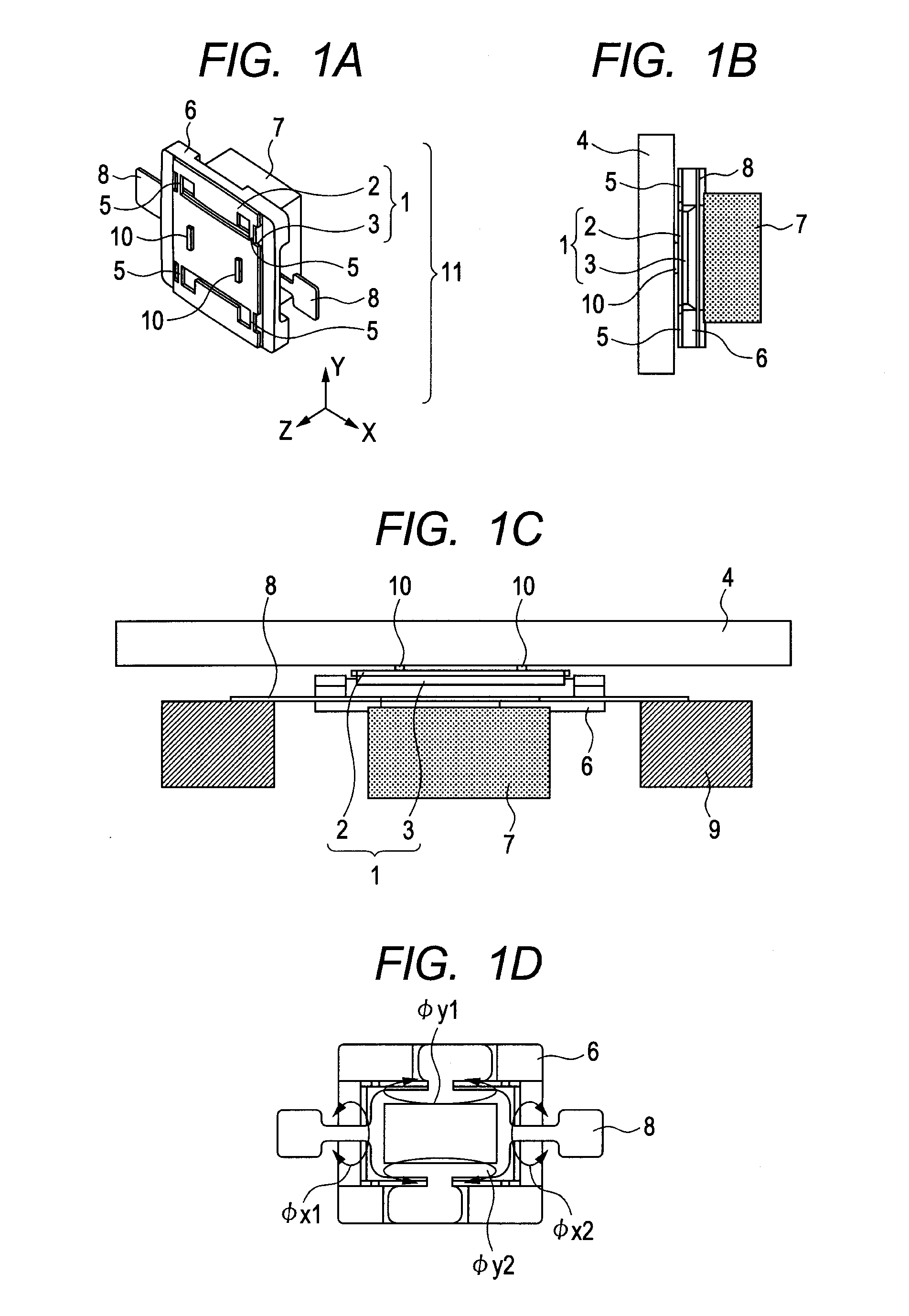
[0052]An example configuration of a vibration wave actuator, to which the present invention is applied, will be described with reference to FIGS. 3A and 3B. In the vibration wave actuator, a driven element that is in contact with a plurality of vibrators is moved in a plurality of different directions. The example configuration of the present embodiment includes a plurality of vibrators, and the plurality of vibrators is arranged at positions where the directions of forces generated by elliptic motion are different. The configuration is provided so that the driven element that is in pressure contact with the vibrators via contact members of the vibrators is moved in a predetermined movement direction formed by combining the forces in different directions.

[0053]FIG. 3A is a top view of the vibration wave actuator of the present configuration, and FIG. 3B is a side view of the same. In FIG. 3A, a driven element 4 is not illustrated. The configuration in FIGS. 3A and 3B includes: vibra...

embodiment 2

[0074]An example configuration of a vibration wave actuator according to embodiment 2 will be described with reference to FIG. 4. The overall configuration of the vibration wave actuator is generally similar to the configuration in FIGS. 3A and 3B, which have been described in embodiment 1, and thus, a description thereof will be omitted. The present embodiment will be described only in terms of differences from embodiment 1. A vibrator 1 is configured by joining a vibration plate 2, which includes an elastic body of, e.g., a metal, and an electro-mechanical energy conversion element 3. A driven element 4 includes a magnetic substance.

[0075]The vibrator 1 is connected to a vibrator holding portion 6 via first elastic members 13 formed by narrowing parts of the vibration plate 2 to have a stiffness lower than that of the vibrator as well as to have elasticity. As a result of holding the vibrator 1 as described above, vibration is unlikely to be hindered. Each first elastic member 13 ...

embodiment 3

[0078]An example configuration of a vibration wave actuator according to embodiment 3 will be described with reference to FIG. 5. The overall configuration of the vibration wave actuator in this embodiment is generally similar to those of embodiments 1 and 2. A description will be provided only in terms of differences from embodiments 1 and 2. The vibrator 1 is configured by joining a vibration plate 2, which includes an elastic body of, e.g., a metal, and an electro-mechanical energy conversion element 3. A driven element 4 includes a magnetic substance.

[0079]The vibrator 1 is connected to a vibrator holding magnet 14, which includes a magnet, via first elastic members 5 formed by narrowing the width of parts of the vibration plate 2 to have a stiffness lower than that of the vibrator as well as to have elasticity. As a result of the vibrator 1 being held as described above, vibration is unlikely to be hindered.

[0080]The vibrator holding magnet 14 attracts the driven element 4 towa...


PUM


Abstract

Provided is a vibration wave actuator including: a vibrator including at least an electro-mechanical energy conversion element and an elastic body to which the electro-mechanical energy conversion element is joined, the elastic body including a contact portion formed therein, the vibrator being configured to provide elliptic motion to the contact portion; and a driven element that is in pressure contact with the contact portion of the vibrator, the driven element being moved by the elliptic motion, wherein the vibration wave actuator includes a vibrator holding portion that holds the vibrator via a first elastic member having a stiffness lower than that of the vibrator; and wherein a magnet is arranged on the vibrator holding portion, the driven element includes a magnetic substance, and the contact portion of the vibrator and the driven element are brought into pressure contact with each other by an attraction force of the magnet.

Description

BACKGROUND OF THE INVENTION[0001]1. Field of the Invention[0002]The present invention relates to a vibratory drive apparatus, such as a vibration wave actuator, and specifically relates to a vibratory drive apparatus that is favorable for use in, e.g., a mechanism that corrects blurring due to hand movements in an optical apparatus such as a camera or binoculars, or a drive mechanism for a table.[0003]2. Description of the Related Art[0004]Conventionally, vibration wave actuators, which are vibratory drive apparatuses that move a driven element in contact with a plurality of vibrators in a plurality of different directions (desired directions), are known. Among such vibration wave actuators, a pressure application-type vibration wave actuator in which a magnet is employed for a driven element is known (Japanese Patent Application Laid-Open No. 2009-027769). Also, Japanese Patent Application Laid-Open No. 2007-312519 proposes a vibratory drive apparatus in which a magnetic member is ...

Claims


Application Information

Patent Timeline
IPC IPC(8): H02N2/04
CPCG02B27/646H02N2/0015H02N2/0055H02N2/04H02N2/028H04N5/23264H04N5/2328H02N2/026H04N23/682H04N23/685
Inventor ODA, YUKIKOJIMA, NOBUYUKI
Owner CANON KK
Why Eureka
Try Eureka