Motor driving device and electric equipment using the same

Inactive Publication Date: 2011-11-17
PANASONIC CORP
View PDF2 Cites 63 Cited by
  • Summary
  • Abstract
  • Description
  • Claims
  • Application Information

AI Technical Summary

Benefits of technology

[0011]Therefore, in the motor driving device of the present invention, even in drive at high speed/under high load, the drive is stable and a driving range is e

Problems solved by technology

Therefore, stable drive performance can be obtained when load i

Method used


Image

  • Motor driving device and electric equipment using the same
  • Motor driving device and electric equipment using the same
  • Motor driving device and electric equipment using the same

Examples


first exemplary embodiment

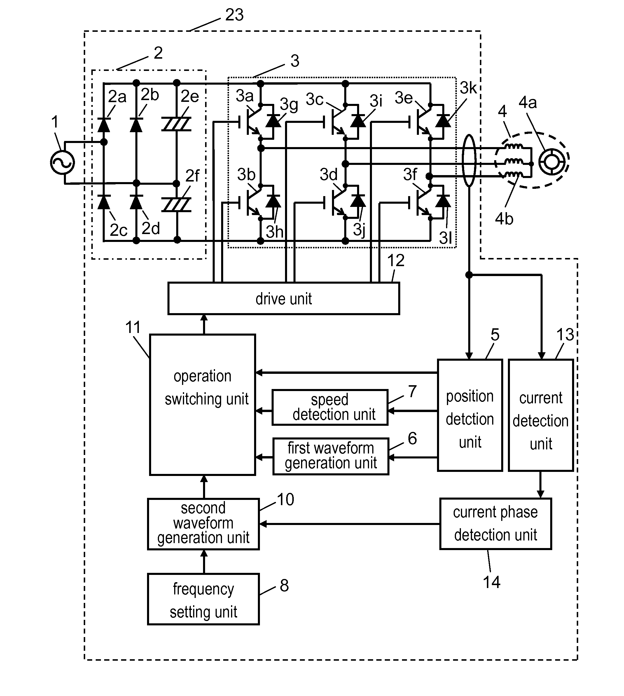
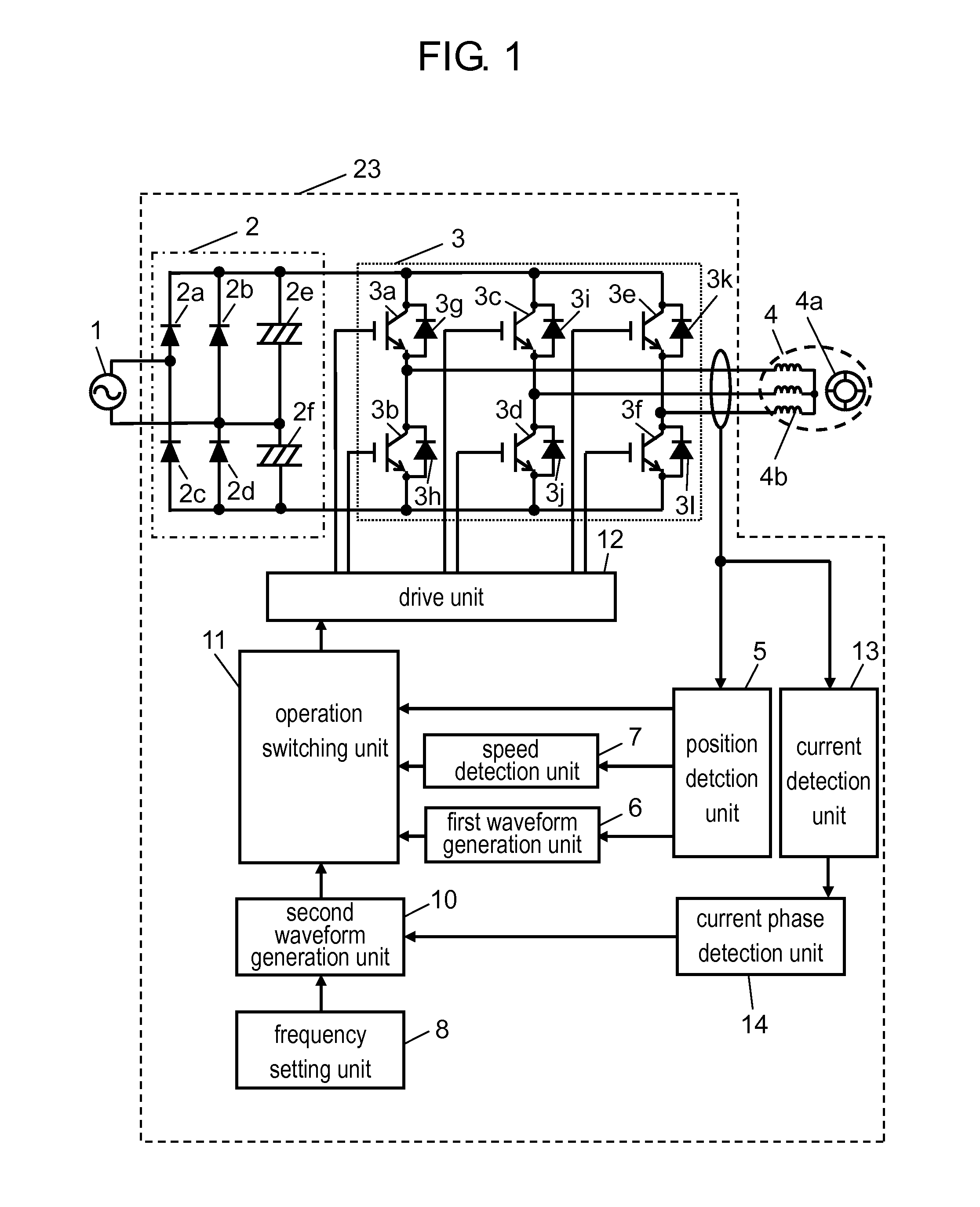
[0031]FIG. 1 is a block diagram showing a motor driving device in accordance with a first exemplary embodiment of the present invention. In FIG. 1, AC power supply 1 is a general commercial power supply. In Japan, it is a 50 Hz or 60 Hz power supply having an effective value of 100 V. Motor driving device 23 is connected to AC power supply 1 and drives brushless DC motor 4. Hereinafter, motor driving device 23 is described.

[0032]Rectifying and smoothing circuit 2 receives an input of AC power supply 1 and rectifies and smoothes AC electric power to DC electric power. Rectifying and smoothing circuit 2 includes four bridge-connected rectifier diodes 2a to 2d, and smoothing capacitors 2e and 2f. In this exemplary embodiment, rectifying and smoothing circuit 2 is made of a voltage doubler rectifying circuit, but rectifying and smoothing circuit 2 may be made of a full-wave rectifying circuit. Furthermore, in this exemplary embodiment, AC power supply 1 is a single-phase AC power supply...

second exemplary embodiment

[0080]FIG. 11 is a block diagram showing a motor driving device in accordance with a second exemplary embodiment of the present invention. The same components as those described in the first exemplary embodiment are described with the same reference numerals given.

[0081]Motor driving device 23 of this exemplary embodiment detects a phase of a current in a winding of stator 4b (for example, a zero-crossing point) by position detection unit 5. Specifically, a current phase is detected from a terminal voltage of inverter 3. Furthermore, motor driving device 23 includes waveform correction unit 9 for correcting a second waveform signal generated by a second waveform generation unit. The second waveform signal transmitted to operation switching unit 11 is corrected via waveform correction unit 9. At this time, in order to prevent abnormality in drive of brushless DC motor 4 in advance, protective control is carried out. The protective control is carried out by protection unit 16. Further...

third exemplary embodiment

[0113]FIG. 15 is a block diagram showing electric equipment using a motor driving device in accordance with a third exemplary embodiment of the present invention. In FIG. 15, the same reference numerals are given to the same components as in FIGS. 1 and 14.

[0114]Brushless DC motor 4 is connected to compression element 18 to form compressor 19. In this exemplary embodiment, compressor 19 is used in a refrigerating cycle. In other words, a high-temperature and high-pressure refrigerant discharged from compressor 19 is transmitted to condensation device 20, and it is liquefied, made to be low pressure in capillary tube 21, evaporated in evaporator 22, and returned to compressor 19 again. Furthermore, in this exemplary embodiment, the case in which the refrigerating cycle using motor driving device 23 is used for refrigerator 24 as electric equipment is described. Evaporator 22 cools inside 25 of refrigerator 24. In this way, in this exemplary embodiment, brushless DC motor 4 drives com...


PUM


Abstract

Brushless DC motor (4) is driven based on a first or second waveform signal output from operation switching unit (11), which switches output so that a first waveform signal by first waveform generation unit (6) is output when the speed of rotor (4a) is determined to be lower than a predetermined speed, and a second waveform signal by second waveform generation unit (10) is output when the speed of rotor (4a) is determined to be higher than the predetermined speed. Thus, there is provided a motor driving device in which drive is stable even at high speed/under high load, and a driving range is extended.

Description

TECHNICAL FIELD[0001]The present invention relates to a motor driving device for driving a brushless DC motor and electric equipment using the same.BACKGROUND ART[0002]A conventional motor driving device drives a motor by switching between speed feedback drive and speed open-loop drive according to a current value or drive speed as disclosed in, for example, Patent Literature 1. FIG. 16 shows a conventional motor driving device described in Patent Literature 1.[0003]In FIG. 16, DC power supply 201 inputs DC power into inverter 202. Inverter 202 is configured by three-phase bridge connecting six switching elements. Inverter 202 converts the input DC power into AC power having a predetermined frequency, and inputs it into brushless DC motor 203.[0004]Position detection unit 204 obtains information on an induced voltage generated by the rotation of brushless DC motor 203 based on a voltage of an output terminal of inverter 202. Based on the information, position detection unit 204 dete...

Claims


Application Information

Patent Timeline
IPC IPC(8): H02P6/14H02H7/093
CPCH02P6/181H02P2203/05H02P6/188H02P6/182
Inventor TANAKA, HIDEHISATAKEOKA, YOSHINORI
Owner PANASONIC CORP
Why Eureka
Try Eureka