Scanning method for determining a touch position of a touch input apparatus

a touch input and scanning method technology, applied in the direction of instruments, computing, electric digital data processing, etc., can solve the problem of limited response rate and achieve the effect of improving the response time of the touch input apparatus and speeding up scanning efficiency

Active Publication Date: 2011-11-17
WACOM CO LTD
View PDF2 Cites 5 Cited by
  • Summary
  • Abstract
  • Description
  • Claims
  • Application Information

AI Technical Summary

Benefits of technology

[0005]An object of the present invention is to provide a scanning method for determining a touch position of a touch input apparatus to speed u

Problems solved by technology

For the conventional method, the response rate is limited to the number of the senso

Method used


Image

  • Scanning method for determining a touch position of a touch input apparatus
  • Scanning method for determining a touch position of a touch input apparatus
  • Scanning method for determining a touch position of a touch input apparatus

Examples


Embodiment Construction

[0013]The detailed description of the present invention will be discussed in the following embodiments, which are not intended to limit the scope of the present invention, but can be adapted for other applications. While drawings are illustrated in details, it is appreciated that the scale of each component may not be expressly exactly.

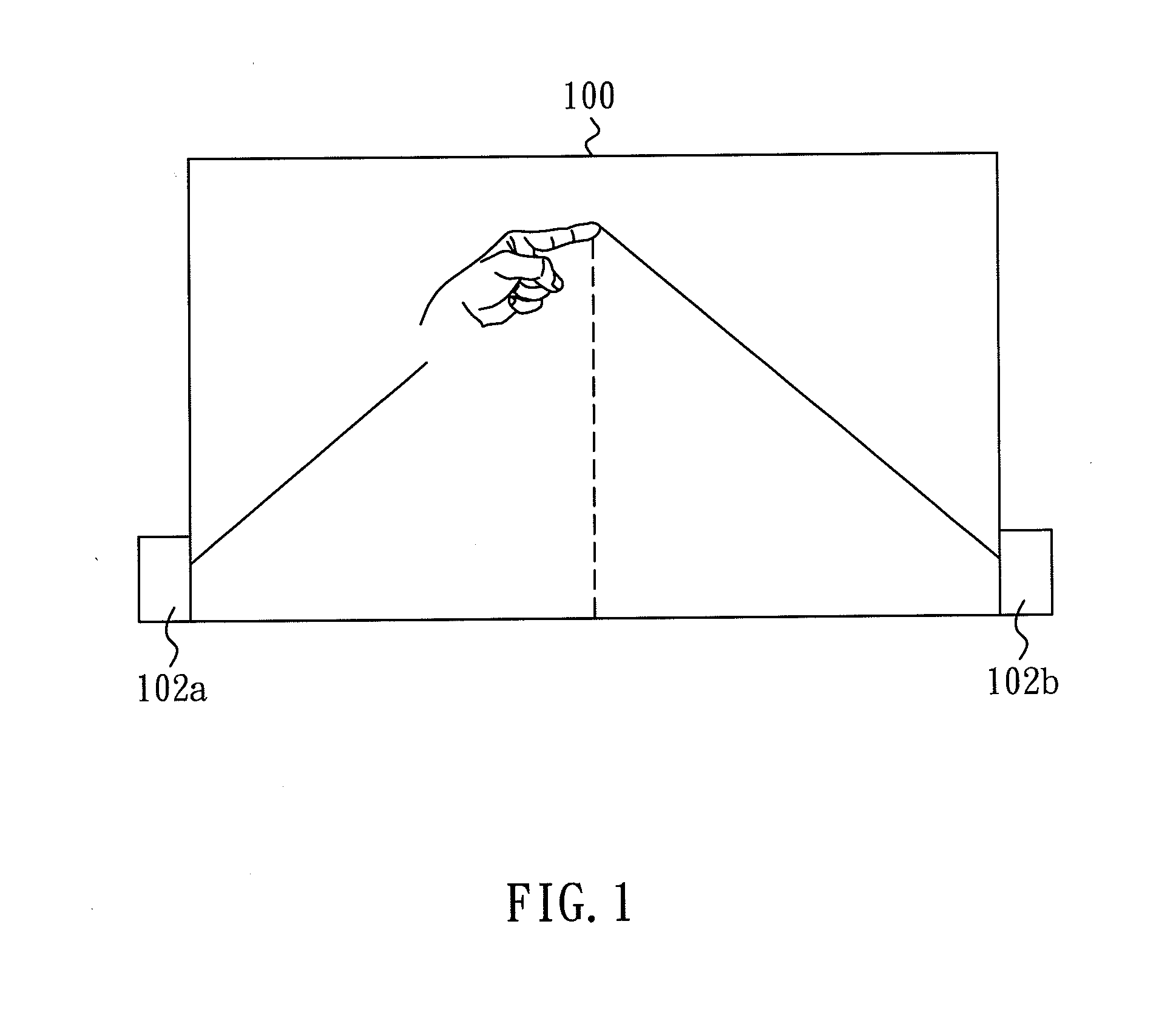
[0014]FIG. 1 shows a schematic diagram of a touch input apparatus according to one embodiment of the invention. The location of a pointer or indicator in a sensing area 100 such as a user's finger or a stylus or a pen is determined through the reflection and detection of light emitted from and received by the light emitting and receiving modules 102a and 102b located at the corners of the sensing area 100. When the pointer or indicator such as a user's finger or a stylus approaches the sensing area 100, the lights emitted from the light emitting and receiving modules 102a and 102b toward the pointer are blocked and reflected back to the light emitting...


PUM


Abstract

A scanning method for determining the touch position of a touch input apparatus is disclosed. First of all, a first exposure process on light sensors of the touch input apparatus by light emitting device of the touch input apparatus is performed. Then the light sensors are scanned. A light sensor generating a signal with a maximum value is located. A region of partial scan of the light sensors is determined according to the position of the light sensor generating the signal with the maximum value. A second exposure process is performed on the light sensors. Then the light sensors within the region of partial scan are scanned. A light sensor generating a signal with a maximum value within the region of partial scan is located and a next region of partial scan is determined. The maximum value of the signal is calculated and the maximum value of the signal is compared to a predetermined value to determine whether the maximum value is higher than the predetermined value.

Description

1. FIELD OF THE INVENTION[0001]The present invention relates to a scanning method for determining a touch position of a touch input apparatus, and more particularly to a scanning method for determining a touch position of a touch input apparatus which can improve the efficiency and shorten the reaction time.2. DESCRIPTION OF THE PRIOR ART[0002]Apparatuses which apply touch technologies to input instruction or information such as displays with touch function can accurately locate the coordinates of touch points within effective sensing range. Among various techniques of detecting the coordinates of touch points on the surface of a display, one technique of detecting the coordinate of a touch point is to locate the light emitting module and the light sensor module on opposing sides of a display respectively. The position of the touch point is detected by the position of the sensor of the light sensor module which does not receive light emitted from the corresponding the light emitter ...

Claims


Application Information

Patent Timeline
IPC IPC(8): G06F3/042
CPCG06F3/0428
Inventor CHEN, WEI-CHOUHSU, CHUNG-WEN
Owner WACOM CO LTD
Why Eureka
Try Eureka