
Wireless relay device

Inactive Publication Date: 2011-11-17
BUFFALO CORP LTD
View PDF3 Cites 21 Cited by
  • Summary
  • Abstract
  • Description
  • Claims
  • Application Information

AI Technical Summary

Benefits of technology

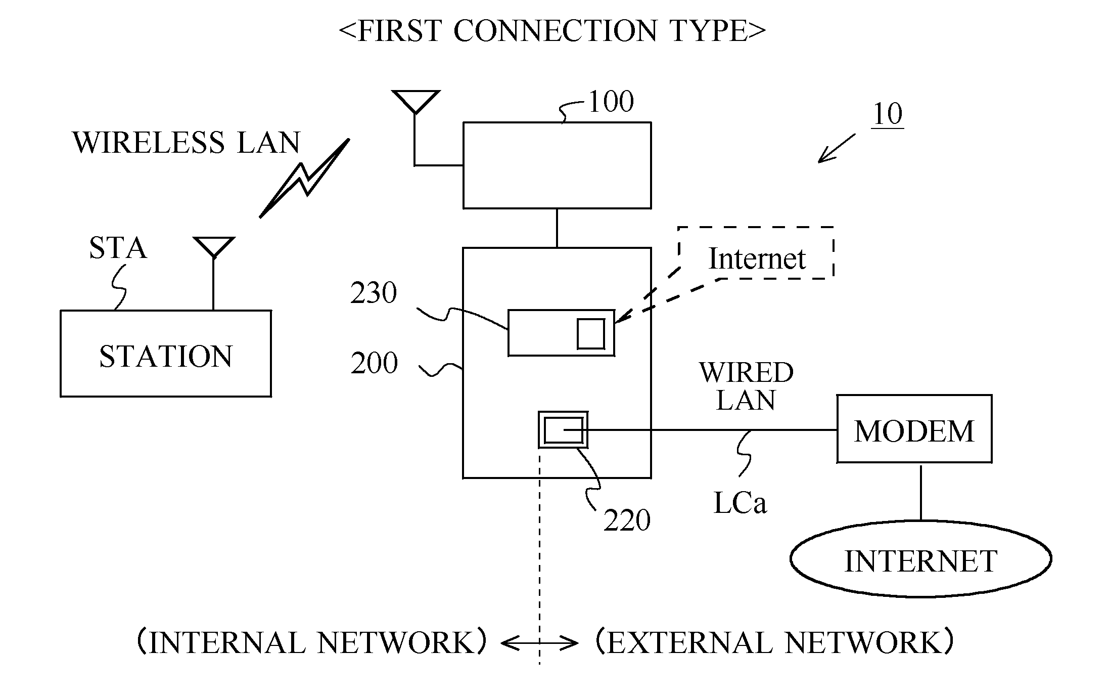
[0008]An object of the present invention, brought about to resolve the above-described problems, is to make available a wireless relay device in which a solely provided port is rendered usable both as an external-network-side port and an internal-network-side port.

Problems solved by technology

Thus, the development of technology for using the lone port that the access points provide not only as an external-network-side port but also as an internal-network-side port is a forthcoming issue.
At present, however, technology serviceable for using the lone port that the access points provide both as an external-network-side port and as an internal-network-side port has yet to be realized.
It should be noted that problems of this sort have of course also existed for access points furnished with a plurality of ports, in that if each port is considered singly, situations in which each port is to be used as an external-network-side port as well as an internal-network-side port may arise.
In addition, problems of this sort are not limited to wireless relay devices that function as a wireless LAN access point, but have been common to wireless relay devices for carrying out wireless communications over any given wireless communications network.

Method used


Image

  • Wireless relay device
  • Wireless relay device
  • Wireless relay device

Examples


first embodiment

(1) First Embodiment

[0046]Next, an operation-mode switching process performed by the wireless relay device 10 having the above exemplified configuration will be described. The operation-mode switching process contemplated by the present invention may be embodied by first and second embodiments. Hereinafter, the operation-mode switching process according to the first embodiment will be described. FIG. 5 is a flowchart representing a procedure for the operation-mode switching process performed by the wireless relay device 10 according to the first embodiment.

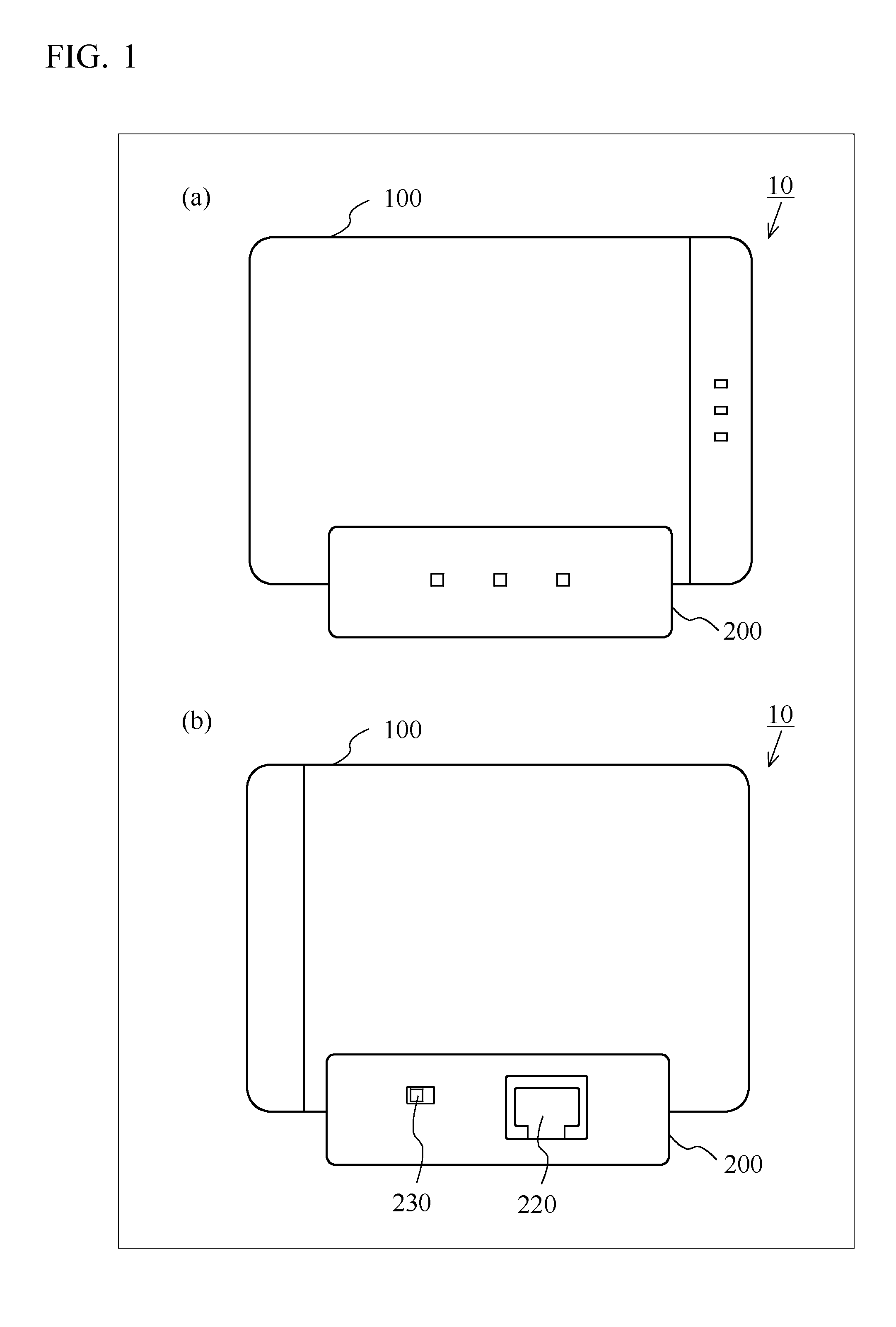
[0047]In FIG. 5, when the main unit 100 is powered on, and a LAN cable LCa (FIG. 6) is connected to the port 220 to form a network link (linkup between the port 220 and a network), the operation-mode switching process according to the first embodiment starts in the main unit 100. The transfer control section 122 monitors via the connection monitoring section 126 whether the main unit 100 and the cradle 200 are connected, and waits...

second embodiment

(2) Second Embodiment

[0080]The above first embodiment describes the configuration in which the main unit 100 is connected to the cradle 200. This second embodiment will describe a connection type which causes a station STA to establish a connection with the Internet even in the case where the main unit 100 is not connected to the cradle 200. FIG. 14 is a flowchart showing the procedure of an operation-mode switching process according to the second embodiment performed by the wireless relay device 10.

[0081]As shown in FIG. 14, if the main unit 100 and the cradle 200 are not connected (No in step S105) when the operation-mode switching process according to the second embodiment has started in the main unit 100, the transfer control section 122 switches the operation mode of the transfer process section 121 to a third operation mode (step S130), which is a procedure different from the operation-mode switching process according to the first embodiment (FIG. 5). The switching to the thir...


PUM


Abstract

A switch switches between an external connection state where a port functions as an external-network-side port, and an internal connection state where the port functions as an internal-network-side port. A transfer process section transfers, when the switch is in the external connection state, a packet between a station belonging to a wirelessly connected internal network and a modem wiredly connected to the port, and otherwise transfers, when the switch is in the internal connection state, a packet between a station wiredly connected to the port and a network device belonging to a wirelessly connected external network.

Description

CROSS REFERENCE TO RELATED APPLICATION[0001]The disclosure of Japanese Patent Application No. 2010-111781, filed on May, 14, 2010, is incorporated herein by reference.BACKGROUND OF THE INVENTION[0002]1. Field of the Invention[0003]The present invention relates to wireless relay devices for carrying out communications relaying processes in wireless communications networks.[0004]2. Description of the Background Art[0005]In homes or offices, in order to connect stations, such as personal computers and game machines, that are on a wireless or wired LAN (Local Area Network) to other networks, access points functioning as a wireless relay device are widely used (see, for example, Japanese Laid-Open Patent Publication No. 2005-142907). Portable access points have been proposed as access points of this sort, for enabling network connection wirelessly in away locations.[0006]With portable access points, because smaller-sized casings are desirable, a configuration in which, for example, only ...

Claims


Application Information

Patent Timeline
IPC IPC(8): H04B7/14H04W84/02
CPCH04W88/10H04W84/105
Inventor YAMADA, DAISUKESONG, HAINIANOHARA, TOMOAKI
Owner BUFFALO CORP LTD
Learn More