
Power module package having improved heat dissipating capability

a power module and heat dissipation capability technology, applied in the field ofsemiconductor packages, can solve the problems of complicated process of manufacturing power module packages, high reliability and good temperature characteristics of power devices, and the inability to completely dissipate so as to achieve the effect of effectively dissipating heat generated in power circuit chips, simple and cheaper manufacturing

Inactive Publication Date: 2006-06-13
SEMICON COMPONENTS IND LLC
View PDF17 Cites 125 Cited by
  • Summary
  • Abstract
  • Description
  • Claims
  • Application Information

AI Technical Summary

Benefits of technology

The design enhances heat dissipation capabilities by 20-30% and simplifies manufacturing, reducing costs by eliminating the need for metal heat sinks and using a single epoxy compound with consistent heat conductivity.

Problems solved by technology

Further, the power devices require high reliability and good temperature characteristics.
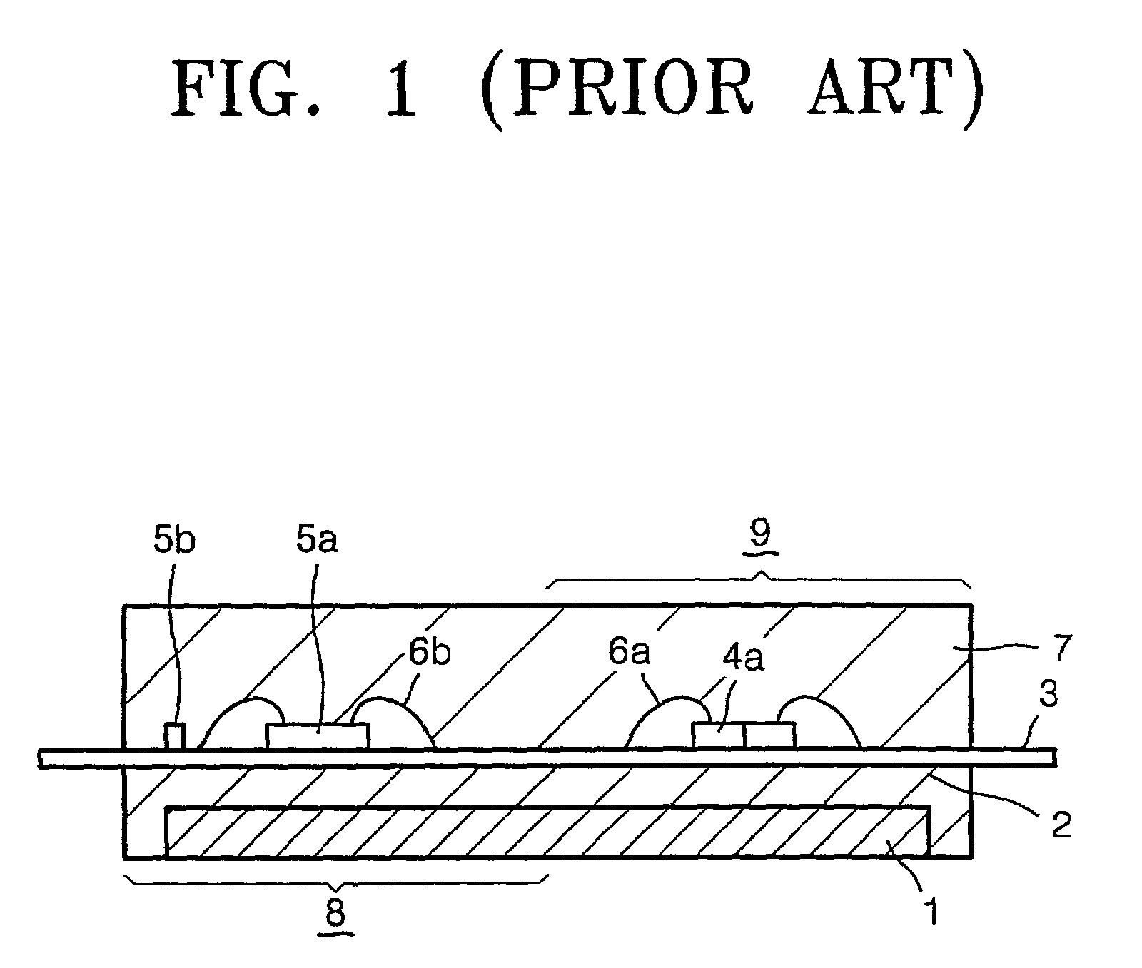
First, the EMC 2 is filled between the backside of the lead frame 3 and the heat sink 1 made of copper in order to maintain insulation properties, and thus there is a limitation in completely dissipating heat generated in the power circuit chip 4a, to the outside of the power module package.
Second, two EMCs having different characteristics are used in one power module package, and thus a process of manufacturing the power module package becomes complicated and it is difficult to perform the process of manufacturing the power module package automatically.
Third, the heat sink 1 made of copper is used in the power module package, and a process of manufacturing the power module package is complicated, and thus a manufacturing cost is increased.

Method used


Image

  • Power module package having improved heat dissipating capability
  • Power module package having improved heat dissipating capability
  • Power module package having improved heat dissipating capability

Examples


Embodiment Construction

[0027]Hereinafter, preferred embodiments of the present invention will be described in detail with reference to the accompanying drawings.

[0028]The arrangement of a power circuit element and a control circuit element which will be described in this specification, and the structure of a lead frame and a heat sink are exemplified, however, this invention is not limited to only the specific shapes shown in drawings and is self-evident to a person skilled in the art.

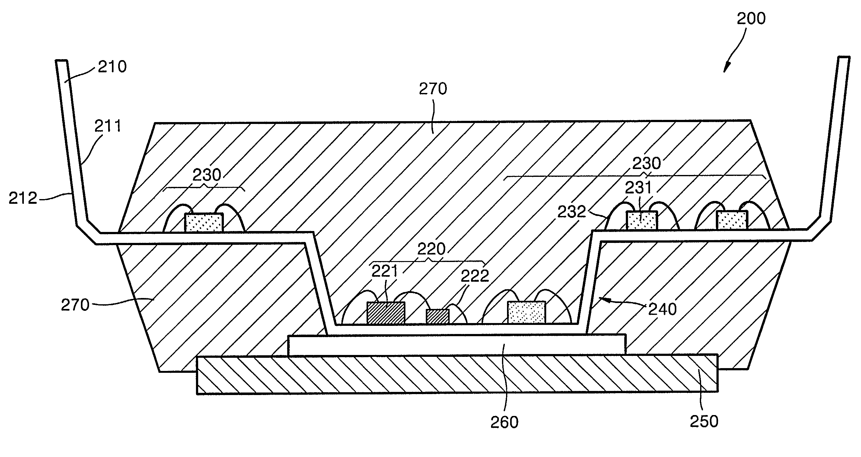
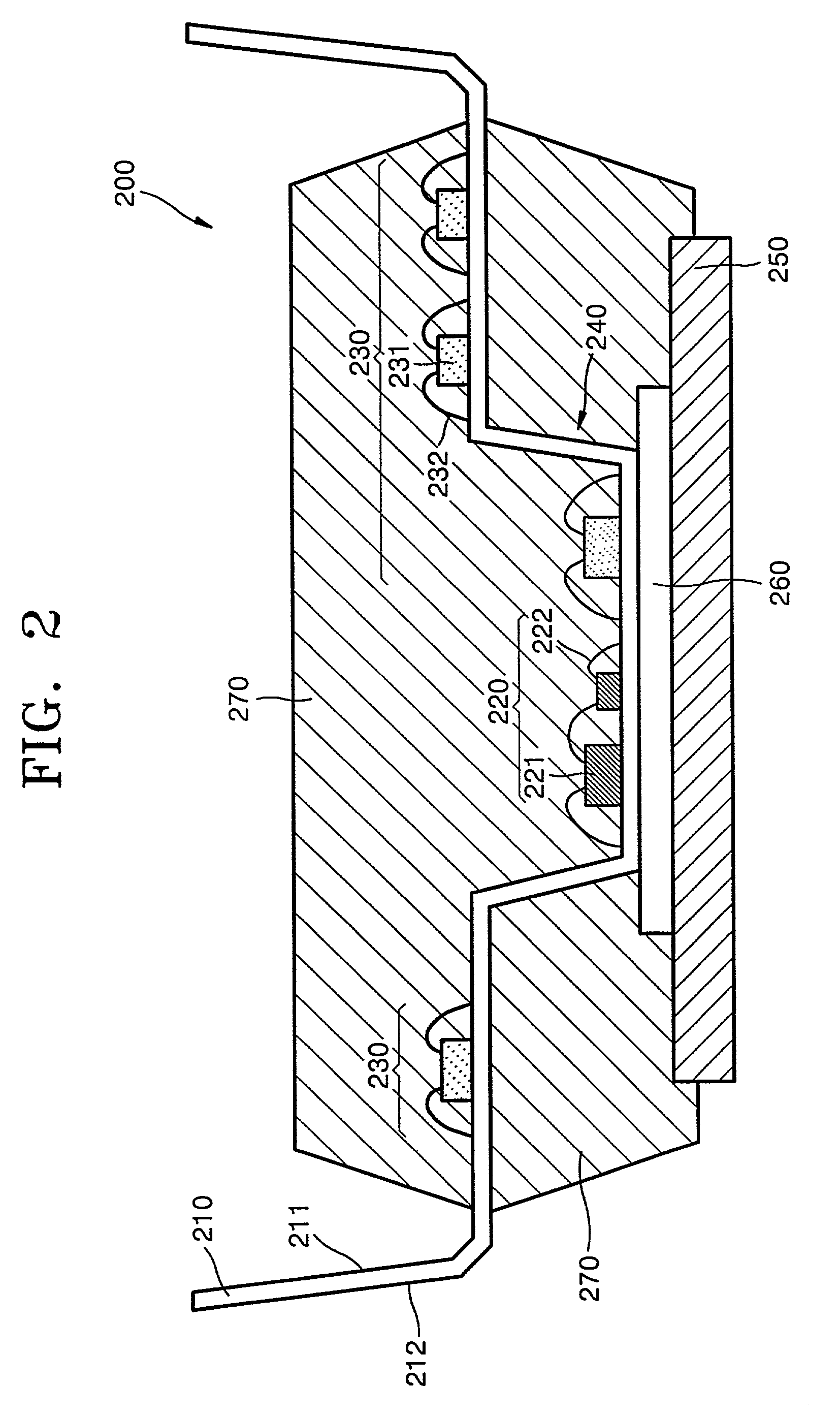
[0029]FIG. 2 is a sectional view of a power module package according to an embodiment of the present invention. Referring to FIG. 2, the power module package 200 includes a lead frame 210, a power circuit element 220, a control circuit element 230, a heat sink 250, and an epoxy molding compound (EMC) 270. The power circuit element 220 includes a power circuit chip 221 and an aluminum wire 222. The aluminum wire 222 has a diameter of about 250–500 μm such that the aluminum wire 222 can withstand a high current rating. The con...


PUM


Abstract

A power module package is provided. The power module package includes a power circuit element, a control circuit element, a lead frame, a heat sink, and an epoxy molding compound (EMC). The control circuit element is connected to the power circuit and controls chips in the power circuit. The lead frame has external connecting means formed at the edges thereof, and a down set part, namely, formed between the external connecting means. The lead frame has a first surface to which the power circuit and the control circuit are attached, and a second surface used as a heat dissipating path, in particular, the power circuit is attached to the down set part. The heat sink which is closely attached to the down set part of the second surface of the lead frame by an adhesive. The EMC surrounds the power circuit, the control circuit, the lead frame and the heat sink, and exposes the external connecting means of the lead frame and a side of the heat sink.

Description

BACKGROUND OF THE INVENTION[0001]1. Field of the Invention[0002]The present invention relates to a semiconductor package, and more particularly, to a power module package having improved heat dissipating capability.[0003]2. Description of the Related Art[0004]In general, in semiconductor packages, one or more semiconductor chips is or are mounted on a chip pad in a lead frame, encapsulated with an epoxy molding compound (EMC) to protect internal parts, and mounted on a printed circuit board (PCB).[0005]However, as high speed, large scale and highly integrated electronic devices have been rapidly developed in recent times, techniques that allow for low cost, miniaturization, and lightweight manufacturing are also required for power devices which are applied to automobiles, industrial equipment and household electrical appliances. Further, the power devices require high reliability and good temperature characteristics. Thus, a power module package for mounting a plurality of semicondu...

Claims


Application Information

Patent Timeline
Patent Type & Authority Patents(United States)
IPC IPC(8): H01L23/495H01L21/56H01L23/433
CPCH01L21/565H01L23/4334H01L23/49575H01L2224/45144H01L2224/45124H01L24/48H01L2924/01079H01L2924/01078H01L2224/48091H01L2224/48137H01L2224/48247H01L2924/01004H01L2924/00014H01L2924/00H01L2224/45015H01L2924/12042H01L2924/12036H01L24/45H01L2924/181H01L2924/2076H01L2924/00015H01L2924/00012
Inventor JEUN, GI-YOUNGPARK, SUNG-MINLEE, JOO-SANGLIM, SUNG-WONJEON, O-SEOBLEE, BYOUNG-OKKIM, YOUNG-GILYANG, GWI-GYEON
Owner SEMICON COMPONENTS IND LLC
Learn More