
Variable media feed system and printhead apparatus

Inactive Publication Date: 2011-11-17
LINDSAY BRETT A +1
View PDF18 Cites 6 Cited by
  • Summary
  • Abstract
  • Description
  • Claims
  • Application Information

AI Technical Summary

Benefits of technology

[0012]The single print media is fed from the high speed feed rollers to the print zone of the printing apparatus. Within the print zone, the slanted printhead is suspended above a slanted floating deck assembly with a deflector plate suspended below the printhead to direct the print medium to the floating deck. The deflector plate is aligned with and at a minimal distance from the slanted feed platform. The print medium is directed below the deflector plate on to the slanted floating deck assembly. The floating deck is normally compressed against the deflector plate therefore as print media of different thicknesses are fed on to the floating deck, the deck is moved at that thickness away from the deflector plate compressing the media against the defector plate and the print head thereby maintaining a constant clearance distance between the printhead and the print media.
[0014]It is another object of the present invention to provide a feed system that accepts a single stacked batch of various thicknesses of media including envelopes, packages or other printable documents and media of different thicknesses and facilitates delivery of singulated media into the print zone to be printed.
[0015]It is yet another object of the present invention to prevent shingling, i.e. the sticking together or stacking of media as the media is fed into the print zone by using a variable size nip to accommodate different thicknesses of media during the transport of the media to the print zone.
[0017]It is another object of the present invention to provide a floating deck having a two dimensional range of motion within the print zone to allow for printing of media of different thicknesses without movement of the printhead.
[0019]It is another object of the present invention that media of varying thicknesses are consecutively transported and printed using a printer apparatus that maintains a consistent clearance distance between a top surface of the media and the printhead of the apparatus.

Problems solved by technology

However, the clearance distance between the ink jetting nozzles and the front side of the print media can only be minimized to a certain extent.
If the clearance distance is too small, waving in the print media caused by wet ink may cause the front side of the print media to touch the printhead in the area of ink jetting nozzles.
When the print media is touching the printhead, the ink drops of course cannot be properly jetted on the front side thereof for formation of a print image.
If the media is too far away from the printhead there will of course be blurring and overspray from the printhead nozzles.
Decrease in clearance distance to improve print quality may result in the print media contacting the printhead which is not desirable as described above.
Likewise, the compressive force applied to print medium 12 in nip 50 by metering rollers 36 may result in a slight cupping of feed roller 20, depending upon the material from which feed roller 20 is constructed.” Either result may be poorer quality print reproductions or damage to the print media.

Method used


Image

  • Variable media feed system and printhead apparatus
  • Variable media feed system and printhead apparatus
  • Variable media feed system and printhead apparatus

Examples


Embodiment Construction

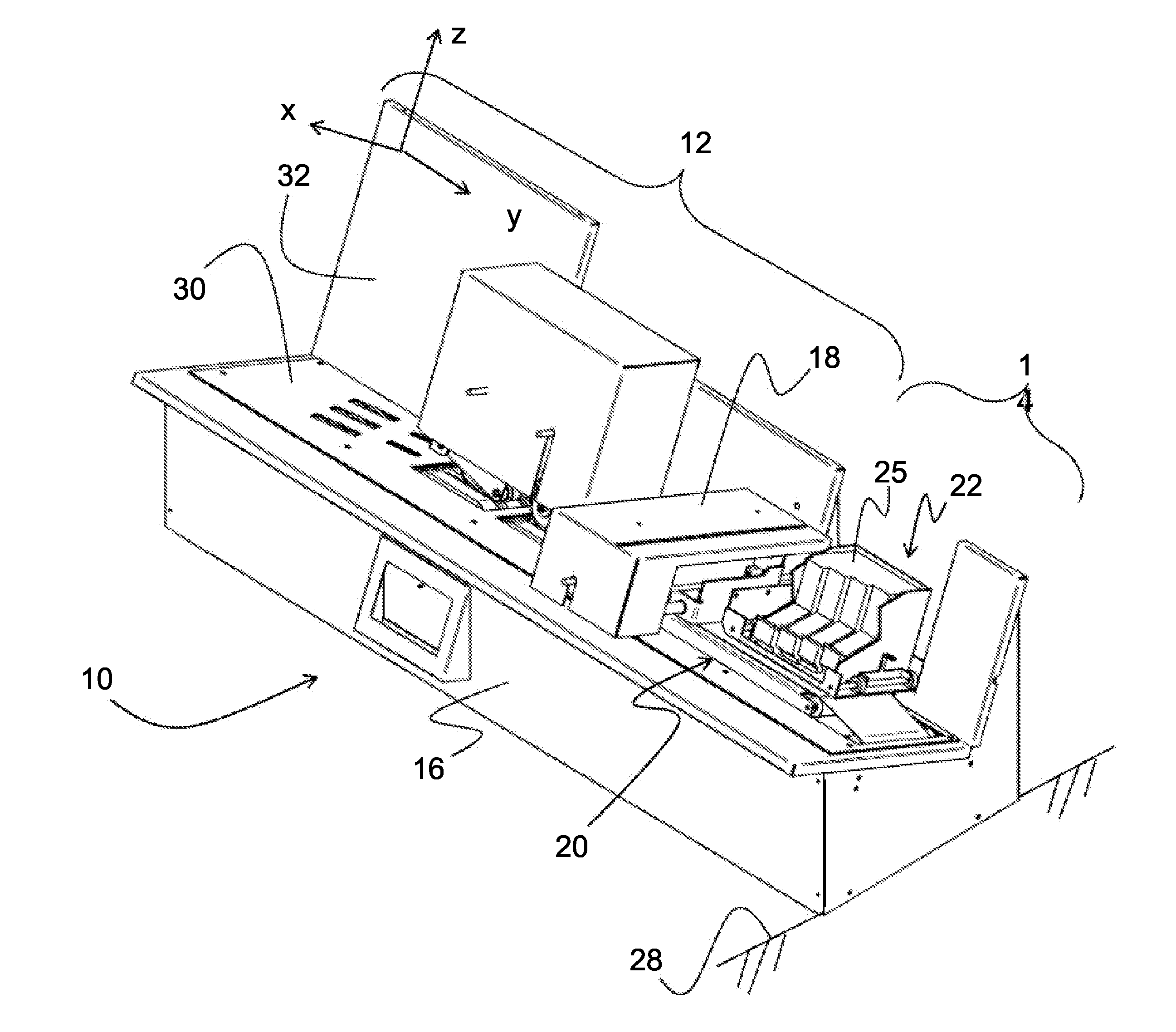
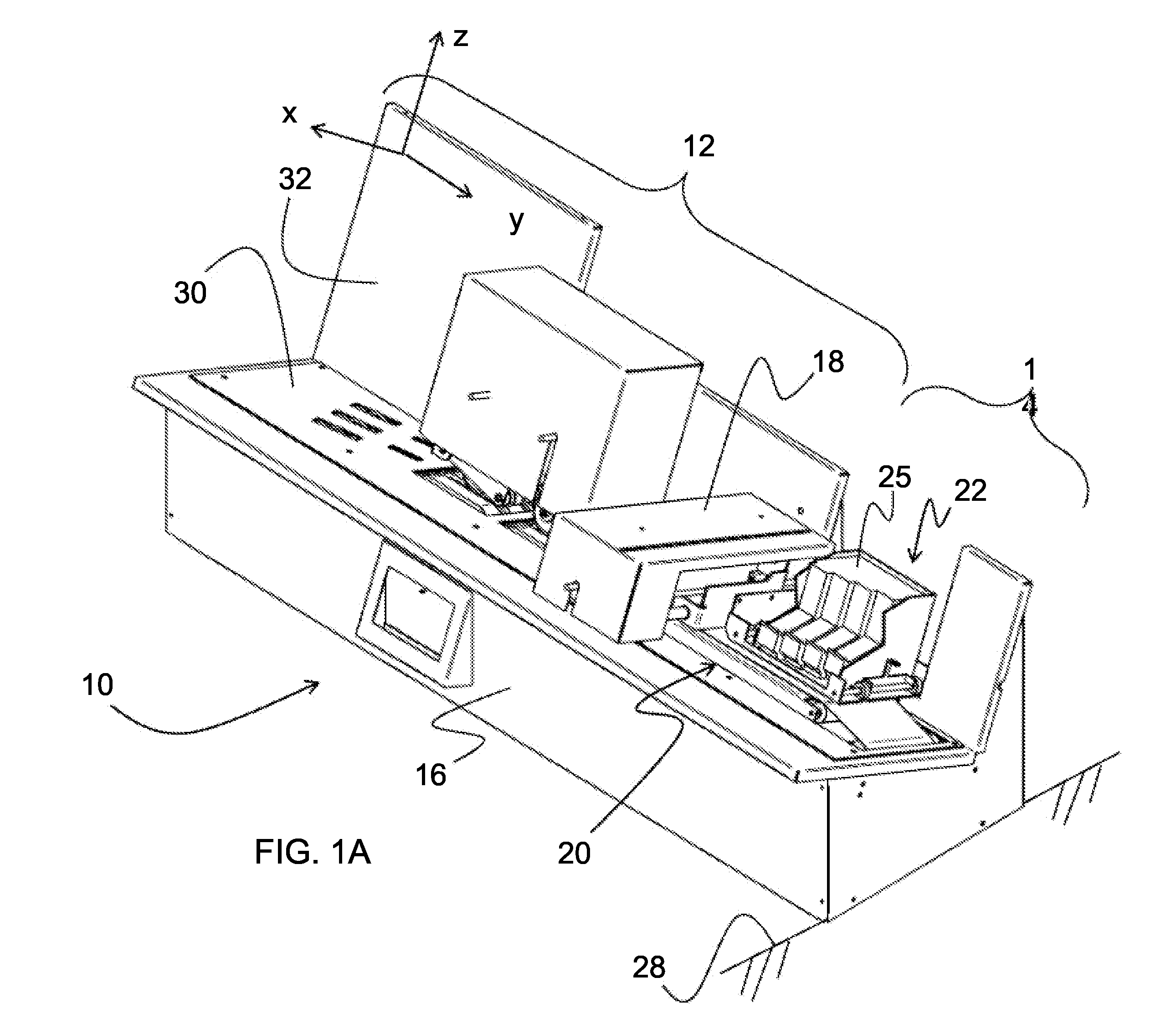
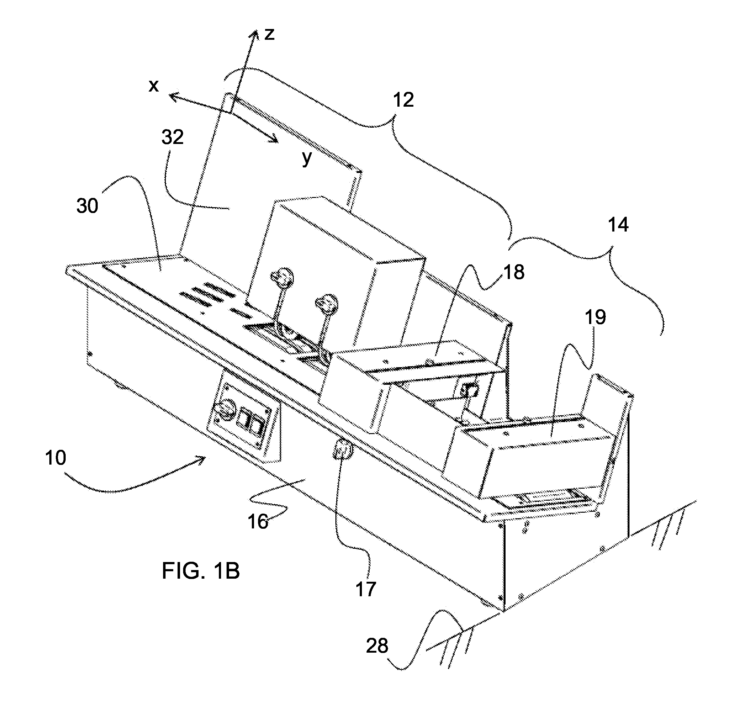
[0043]Referring now to FIG. 1A, a first embodiment of a variable media feed system and printhead apparatus 10 for feeding variable thickness print media through a feed zone 12 to a print zone 14 where ink is jetted or otherwise introduced to the surface of the media. The feed system and printhead apparatus 10 comprises in general a base housing 16 which includes the feed and media alignment components of the feed system and printhead apparatus 10. The feed system includes a feed zone 12 with a plurality of media handling wheels, belts and rollers described in further detail below, leading to a media sensor 18 and then subsequently to a printhead 22 in the print zone 14. Besides the printhead 22, the print zone 14 includes a floating deck 20 to accommodate varying thicknesses of media below the printhead 22. For example the printhead 22 may be a cancellation stamp printing mechanism for repetitive printing of cancellation markings on a mail stamp affixed to each of the individual med...


PUM


Abstract

A print media feed system for media of variable thickness having a slanted loading platform with drive wheels to direct print media to a feed zone having a belt system and hanging friction wheels to draw out single print medium of varying thickness and feed the medium to a print zone for a ink jet, laser or other printer wherein the print zone includes a floating deck to maintain a constant clearance distance between the printhead and the print medium.

Description

[0001]This application claims the benefit of U.S. provisional application No. 61 / 345,551 filed May 17, 2010 and entitled Variable Media Feed System and Printhead Apparatus (Docket No. BRILIN P10AUS), which is hereby incorporated herein by reference in its entirety.FIELD OF THE INVENTION[0002]The present invention relates to a print and media feed system for media of variable thickness and in particular to an apparatus which can feed and print media of variable thickness without shingling, i.e. feeding two separate media stacked or partially stacked, to a print zone of an ink jet, laser jet or other printhead and where the apparatus accounts for varying media thickness supplied consecutively to the printhead without movement of the printhead itself.BACKGROUND[0003]Printers for media generally include a printhead within a print zone where media is fed into alignment beneath the ink nozzles, jet or sprayers of the printhead. The media to be printed for example a postal code or stamp to...

Claims


Application Information

Patent Timeline
IPC IPC(8): B41J11/58B65G59/02
CPCB41J11/0035B41J11/58B65H2701/1916B65H3/5284B65H3/042B65H3/523
Inventor LINDSAY, BRETT A.CARPER, JERRY A.
Owner LINDSAY BRETT A
Learn More