Numerical simulation of airflow within porous materials

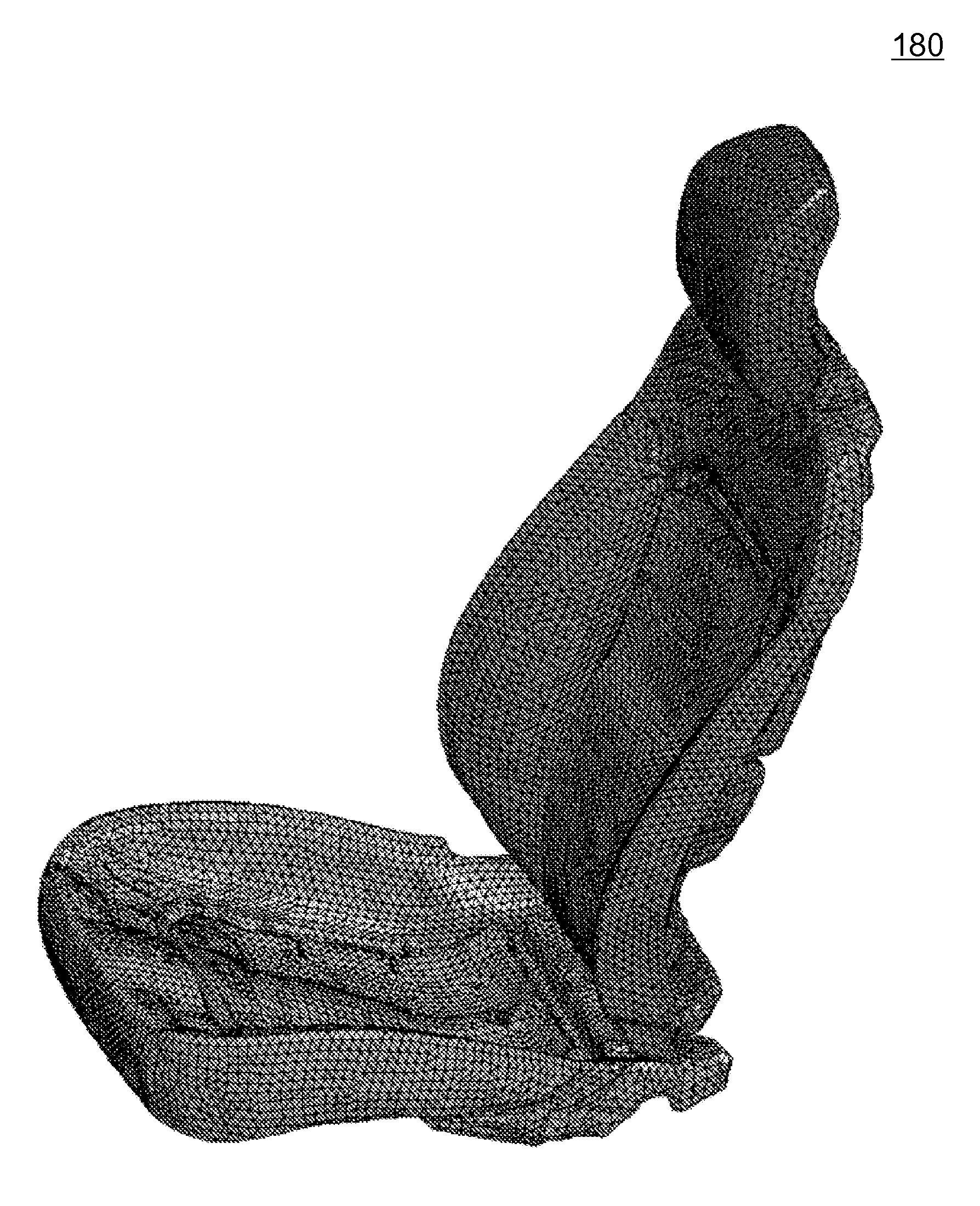
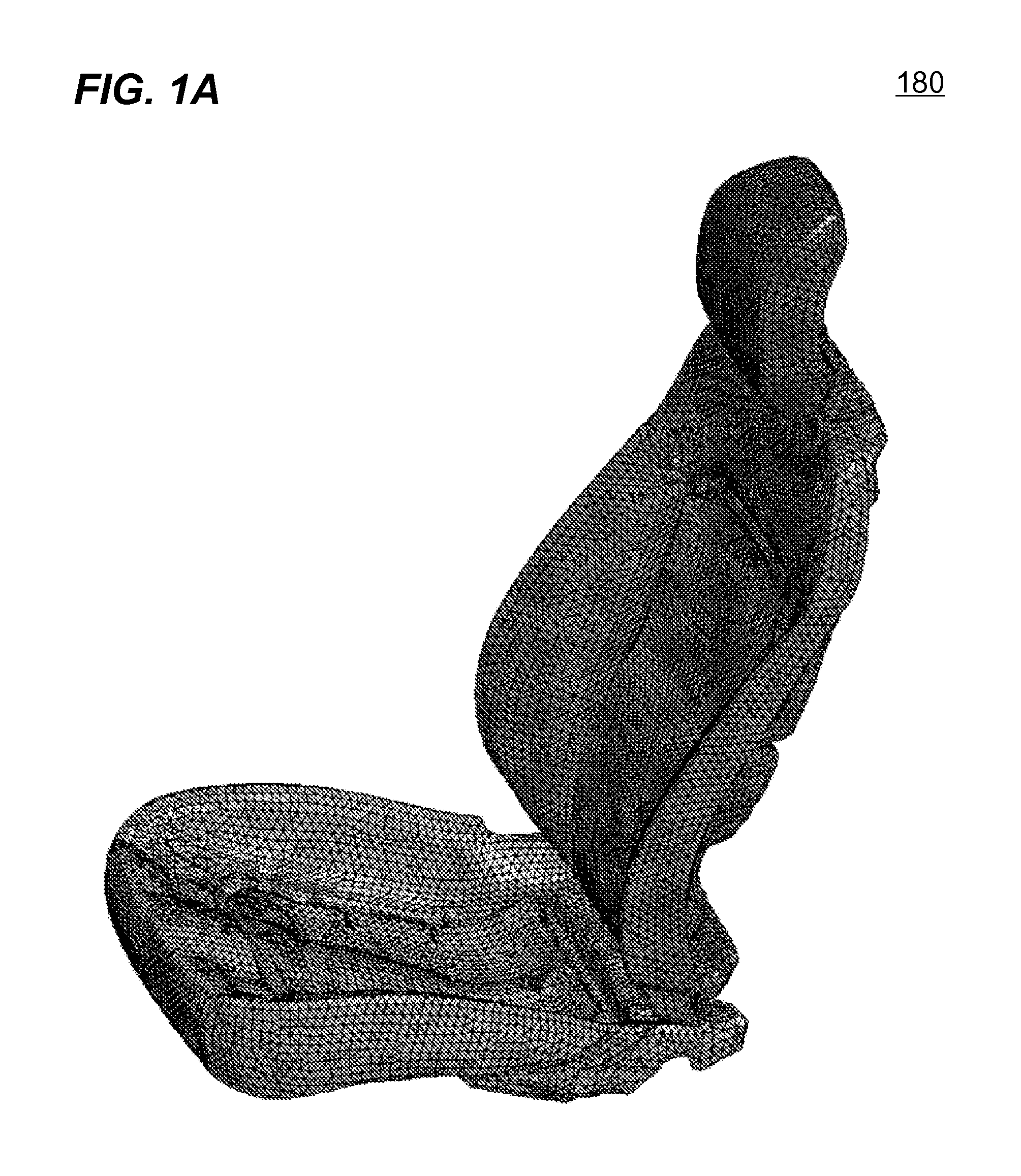
a porous material and numerical simulation technology, applied in the field of numerical simulation of airflow within porous materials, can solve the problem that no prior art approach addresses this requirement, and achieve the effect of constant pore volume ratio

Inactive Publication Date: 2011-11-17
LIVERMORE SOFTWARE TECH
View PDF1 Cites 9 Cited by
  • Summary
  • Abstract
  • Description
  • Claims
  • Application Information

AI Technical Summary

Benefits of technology

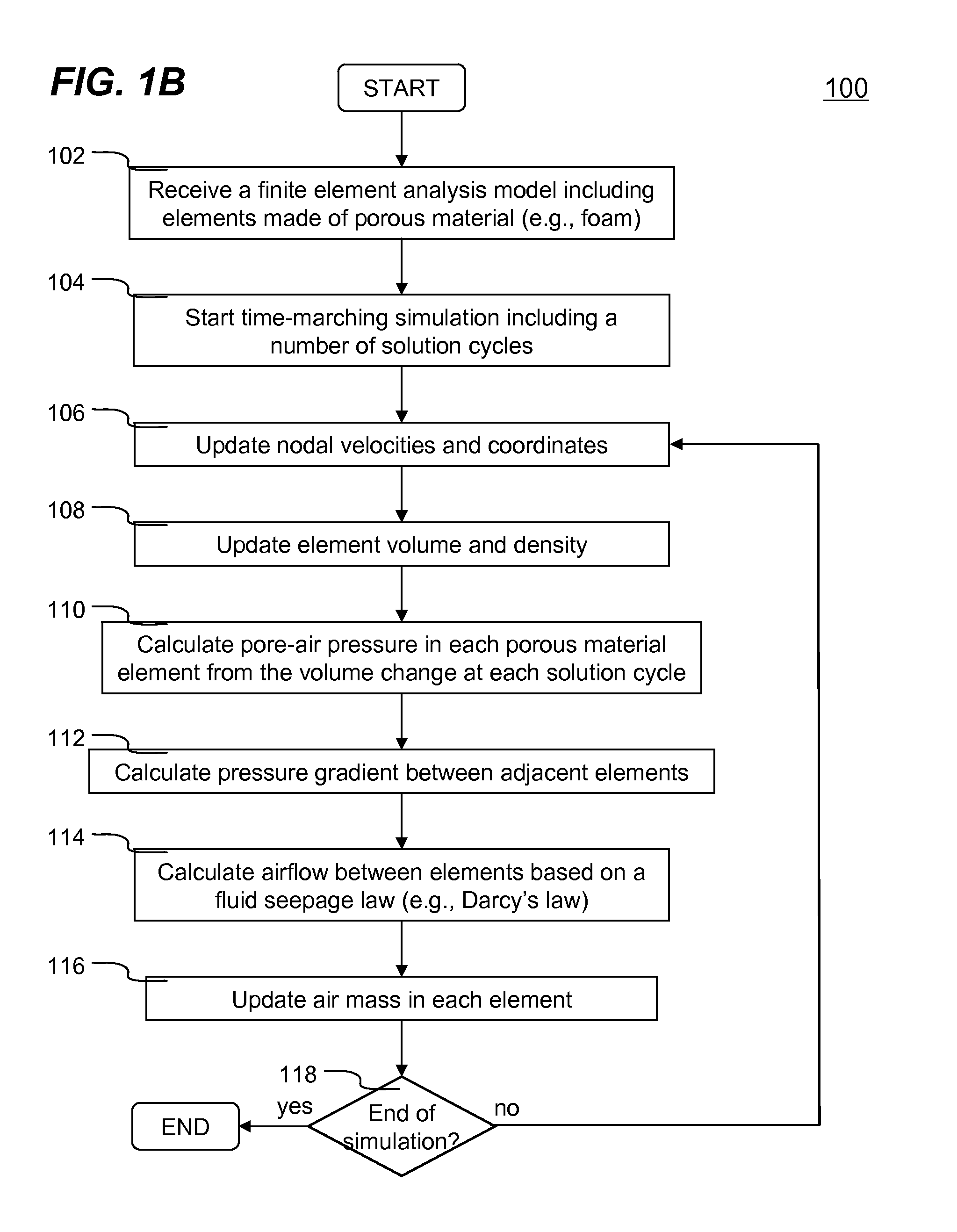
[0008]According to still another aspect, a constant pore volume ratio is used when each finite element of porous material is deformed (e.g., compressed). Pore volume ratio is defined as a constant percentage of pore air in each finite element of porous material. That alleviates the need of iteration to calculate the updated pore air volume and makes this new method a feasible solution to today's CAE analysis need, which requires in-time solution to a model of millions of finite elements.

Problems solved by technology

One of the most challenging FEA tasks is to simulate an impact event such as car crash.
None of the prior art approaches address this requirement.

Method used


Image

  • Numerical simulation of airflow within porous materials
  • Numerical simulation of airflow within porous materials
  • Numerical simulation of airflow within porous materials

Examples


Embodiment Construction

[0019]In the following description, numerous specific details are set forth in order to provide a thorough understanding of the present invention. However, it will become obvious to those skilled in the art that the present invention may be practiced without these specific details. The descriptions and representations herein are the common means used by those experienced or skilled in the art to most effectively convey the substance of their work to others skilled in the art. In other instances, well-known methods, procedures, and components have not been described in detail to avoid unnecessarily obscuring aspects of the present invention.

[0020]Reference herein to “one embodiment” or “an embodiment” means that a particular feature, structure, or characteristic described in connection with the embodiment can be included in at least one embodiment of the invention. The appearances of the phrase “in one embodiment” in various places in the specification are not necessarily all referri...


PUM


Abstract

Systems and methods of numerically simulating airflow within porous materials are disclosed. Engineering product (e.g., car seat) represented by a finite element analysis model containing in part porous material with permeability. In each solution cycle of a time-marching simulation, each of the elements of porous material is evaluated with airflow in conjunction with the traditional mechanical response. Each element's volume change results into different pore air pressure hence a pressure gradient, which in turn is used for airflow calculated in accordance with a fluid seepage law that depends upon permeability of the porous material. Therefore, a more realistic simulation of structural behavior of porous materials can be achieved. The volume change and pressure of each element of porous material is evaluated using ideal gas law. A general form of Darcy's law includes user control parameters is used for evaluating airflow based on the pressure gradient and permeability.

Description

FIELD OF THE INVENTION[0001]The present invention generally relates to computer aided engineering (CAE) analysis, more particularly to numerical simulation of airflow within porous materials in finite element analysis. One exemplary numerical simulation is an automobile crash simulation. In particular, structural responses or behaviors of porous materials of a car seat are simulated using a method according to an embodiment of the present invention.BACKGROUND OF THE INVENTION[0002]Finite element analysis (FEA) is a computer implemented method using a numerical technique for finding approximate solutions of partial differential equations representing complex systems such as three-dimensional non-linear structural design and analysis. The FEA originated from the need for solving complex elasticity and structural analysis problems in civil and aeronautical engineering. With the advance of the computer technology, FEA has become a vital tool for assisting engineers and scientists to mak...

Claims


Application Information

Patent Timeline
Patent Type & Authority Applications(United States)
IPC IPC(8): G06F17/10
CPCG06F17/5018G06F2217/16G06F17/5095G06F30/15G06F30/23G06F2111/10
Inventor YEH, ISHENG
Owner LIVERMORE SOFTWARE TECH
Why Eureka
Try Eureka