Imprint lithography

Active Publication Date: 2011-11-24
ASML NETHERLANDS BV
View PDF4 Cites 4 Cited by
  • Summary
  • Abstract
  • Description
  • Claims
  • Application Information

AI Technical Summary

Benefits of technology

According to a fifth aspect of the invention there is provided an imprint lithography process, comprising moving a first substrate table holding a first substrate to a first position; aligning the substrate to the substrate table at the first position; dispensing an imprintable medium layer on the first substrate at the first position; moving the first substrate to a second position; moving a second substrate table holding a second substrate to the first position; pressing, at the second position, one or more templates in the imprintable medium layer; and aligning the second substrate to the second substrate table during

Problems solved by technology

However, there are problems associated with such reductions.
Current systems are starting to adopt optical sources with wavelengths in the 193 nm regime but even at this level, diffraction limitations become a barrier.
At lower wavelengths, the transparency of materials is very poor.
Optical lithography machines capable of enhanced resolutions require complex optics and rare materials and are consequently very expensive.
The resolution of imprint lithography is limited only by the resolution of the template fabrication process.

Method used


Image

  • Imprint lithography
  • Imprint lithography
  • Imprint lithography

Examples


Embodiment Construction

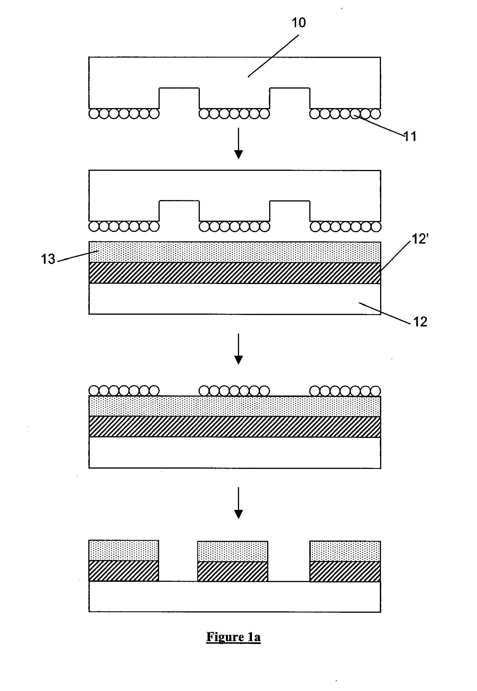
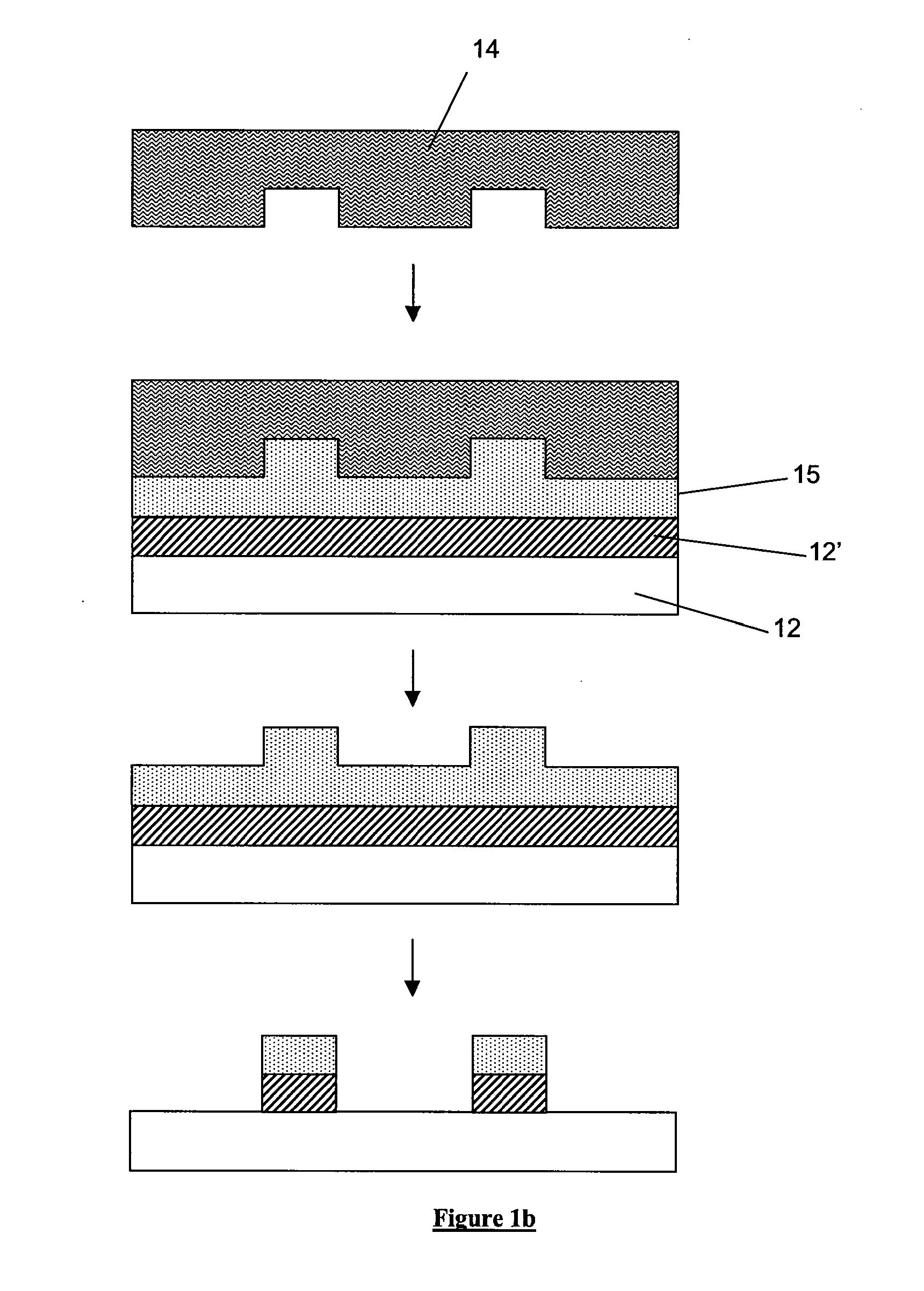
There are two principal approaches to imprint lithography which will be termed generally as hot imprint lithography and UV imprint lithography. There is also a third type of “printing” lithography known as soft lithography. Examples of these are illustrated in FIGS. 1a to 1c.

FIG. 1a schematically depicts the soft lithography process which involves transferring a layer of molecules 11 (typically an ink such as a thiol) from a flexible template 10 (typically fabricated from polydimethylsiloxane (PDMS)) onto a resist layer 13 which is supported upon a substrate 12 and planarization and transfer layer 12′. The template 10 has a pattern of features on its surface, the molecular layer being disposed upon the features. When the template is pressed against the resist layer, the layer of molecules 11 stick to the resist. Upon removal of the template from the resist, the layer of molecules 11 stick to the resist, the residual layer of resist is etched such that the areas of the resist not co...


PUM


Abstract

A lithographic apparatus is disclosed that has a first substrate table arranged to hold a substrate and a second substrate table arranged to hold a substrate, an imprint template holder arranged to hold an imprint template, and an imprintable medium dispenser, wherein the first substrate table is moveable between a first position located at or adjacent to the imprintable medium dispenser, and a second position located at or adjacent to the imprint template holder, and the second substrate table is moveable between the first and second positions, such that the first and second substrate tables swap positions.

Description

FIELDThe present invention relates to imprint lithography.BACKGROUNDA lithographic apparatus is a machine that applies a desired pattern onto a target portion of a substrate. Lithographic apparatus are conventionally used, for example, in the manufacture of integrated circuits (ICs), flat panel displays and other devices involving fine structures.It is desirable to reduce the size of features in a lithographic pattern because this allows for a greater density of features on a given substrate area. In photolithography, the increased resolution may be achieved by using radiation of shorter wavelength. However, there are problems associated with such reductions. Current systems are starting to adopt optical sources with wavelengths in the 193 nm regime but even at this level, diffraction limitations become a barrier. At lower wavelengths, the transparency of materials is very poor. Optical lithography machines capable of enhanced resolutions require complex optics and rare materials an...

Claims


Application Information

Patent Timeline
IPC IPC(8): B05C5/02B05C17/06
CPCB82Y10/00G03F7/0002B82Y40/00G03F9/7042
Inventor SIMON, KLAUS
Owner ASML NETHERLANDS BV
Why Eureka
Try Eureka