Method and apparatus for electrical load control network

Active Publication Date: 2011-11-24
THE WATT STOPPER
View PDF3 Cites 6 Cited by
  • Summary
  • Abstract
  • Description
  • Claims
  • Application Information

AI Technical Summary

Benefits of technology

[0010]The disclosed electrical load control system is based on a free topology wiring scheme that allows any suitable network topologies. e.g., loop, star. wheel, etc. This frees both the wiring designer and the wiring installer from burdensome and time consuming processes that are required using other topologies that require very specific wiring layouts. Less time and less resources are used in design and installation. Thus, energy savings are actually realized sooner in the home or facility design and in the construction process than with conventional systems that require careful wiring layouts in design and installation.

Problems solved by technology

Simple and complex networked load control systems require strict attention to the network topology required for the hardware being used.

Method used


Image

  • Method and apparatus for electrical load control network
  • Method and apparatus for electrical load control network
  • Method and apparatus for electrical load control network

Examples


examples

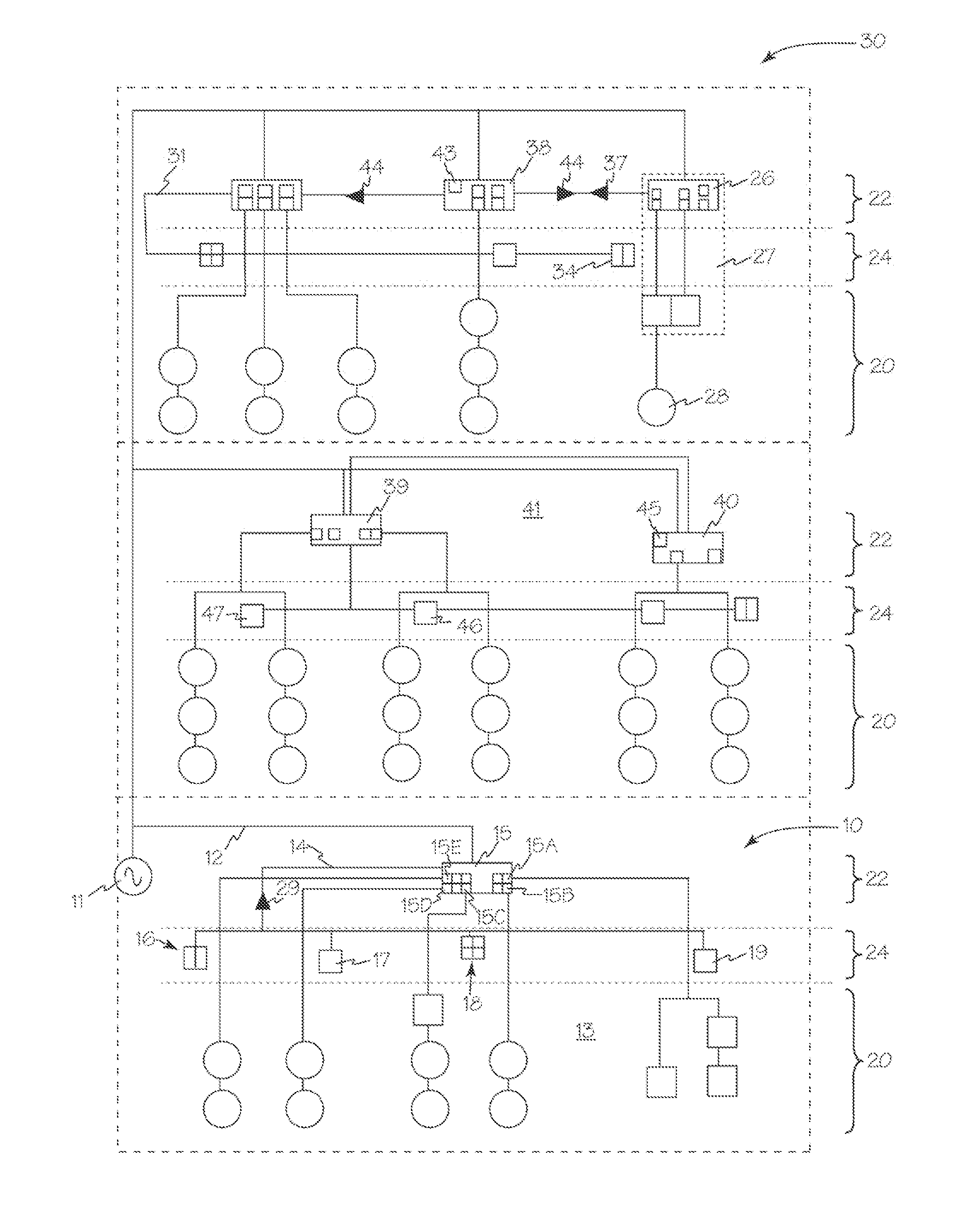
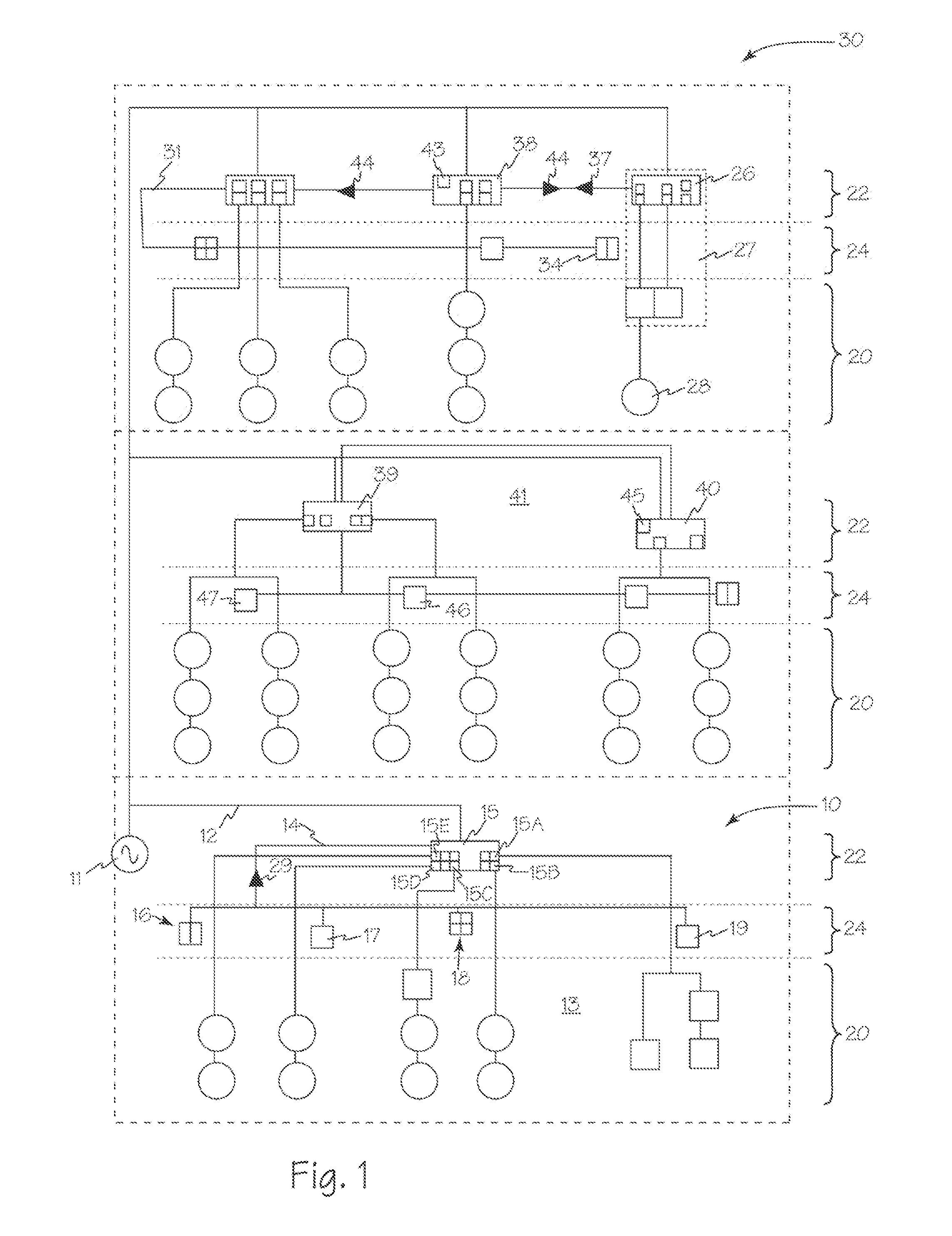
[0140]a. A 3-load on / off room controller and a 1-button wall switch—all loads are bound to the 1-button.

[0141]b. A 3-load room controller and a 2-button wall switch—the first load is bound to the first button, the remaining loads are bound to the second button.

[0142]c. A 3-load room controller and a 3-button wall switch—each load is bound to just one button, first-to-first, second-to-second and third-to-third.

[0143]d. A 3-load room controller and a 4-button wall switch—the first three loads are bound to the first three buttons as described above, the fourth button is unbound and blinks its LED when pressed to indicate its unbound status.

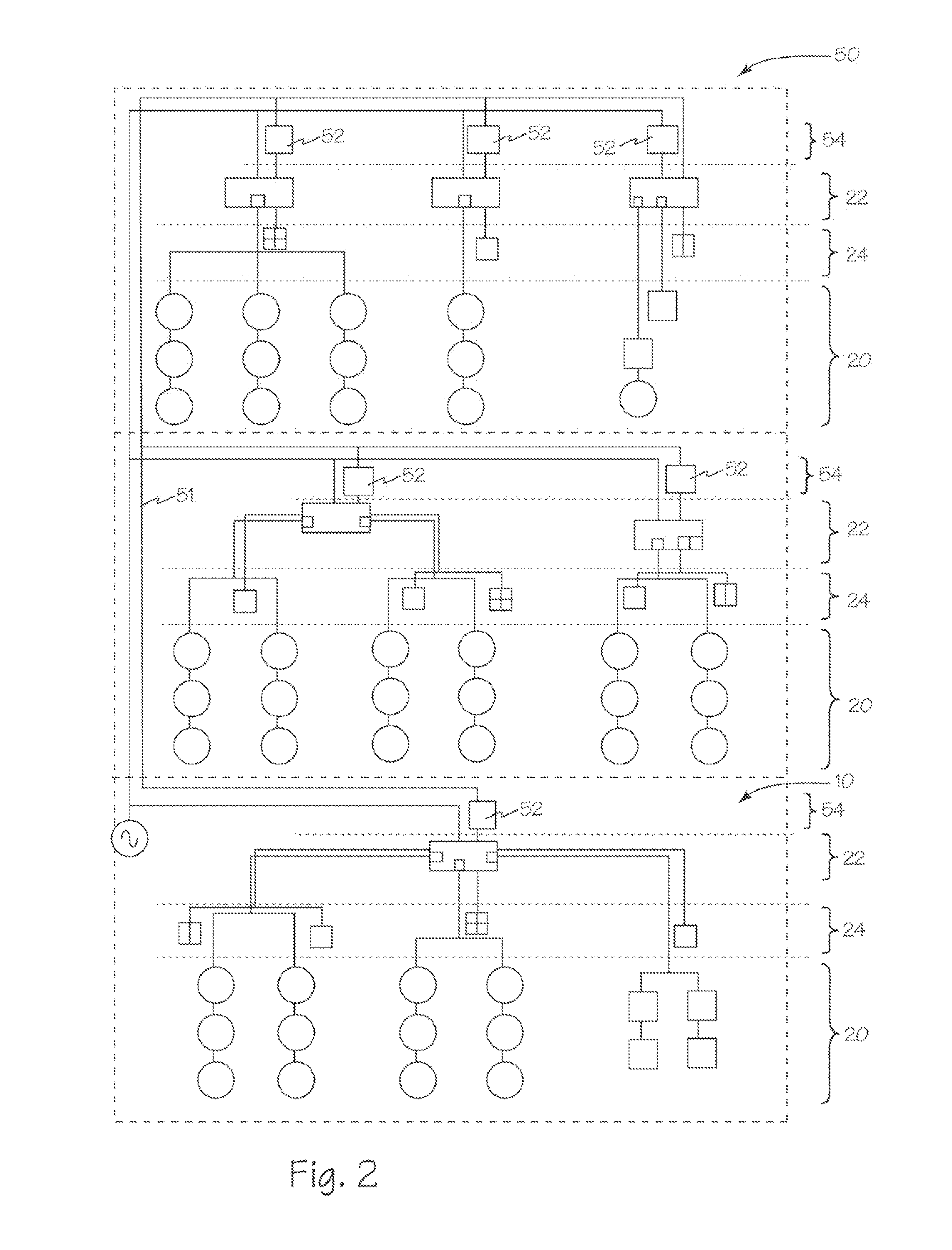
[0144]Referring now to FIG. 2, electrical load control system networks such as systems 10 and 50 may be connected to one another through a standard backbone such as BACNet (Building Automation and Control Network 51. In this case, low voltage power and communication network 14 must have special capability to interface to such a backbone. A separate i...


PUM


Abstract

The methods and apparatus described enable automatic configuration, or commissioning, of controller devices and load control devices through a low voltage communication network controlled by one or more controller devices. These methods and apparatus further enable expansion of the load control system by connection of additional loads and or load control devices and or controller devices which will reinitialize the low voltage communication network and automatically reconfigure the controller devices and load control devices connected to the network.

Description

RELATED APPLICATIONS[0001]This application claims priority from copending U.S. provisional patent application 61 / 215,301 filed May 4, 2009.FIELD OF THE INVENTIONS[0002]The inventions described below relate to the field of electrical load control systems and more specifically to open topology electrical load control networks.BACKGROUND OF THE INVENTIONS[0003]Electrical load control systems have developed from simple knife switch controls to relay control networks with sensors and switches and network control management systems. Simple and complex networked load control systems require strict attention to the network topology required for the hardware being used. Additionally, once properly wired, loads and controls require special tools to link a specific sensor and or control to a specific load.SUMMARY[0004]The methods and apparatus disclosed are directed to an electrical load control system that includes a controller device that is electrically coupled to load control devices. The ...

Claims


Application Information

Patent Timeline
IPC IPC(8): H02J3/00
CPCH02J3/14H02J13/0062Y04S40/124Y02B90/2638Y04S20/222Y02B70/3225H02J2310/12H02J13/00016H02J13/00004Y02B90/20Y04S40/121H02J2310/66H02J13/00007
Inventor WEIDMAN, LOUIAHORTON, PETER JOHNJOYCE, JASON H.FOURNIER, ERIC J.
Owner THE WATT STOPPER
Why Eureka
Try Eureka