Video display device

a video display and video technology, applied in the field of low-power consumption video display devices, can solve the problem that the low-power consumption effect cannot be sufficiently exerted, and achieve the effect of low-power-consumption video display

Inactive Publication Date: 2011-11-24
HITACHI CONSUMER ELECTRONICS CORP
View PDF5 Cites 147 Cited by
  • Summary
  • Abstract
  • Description
  • Claims
  • Application Information

AI Technical Summary

Benefits of technology

[0011]According to the present invention, it is possible

Problems solved by technology

For this reason, in the local dimming control used in the tandem backlight, there

Method used


Image

  • Video display device
  • Video display device
  • Video display device

Examples


Embodiment Construction

[0038]Hereinafter, an embodiment of the present invention will be described with reference to the accompanying drawings.

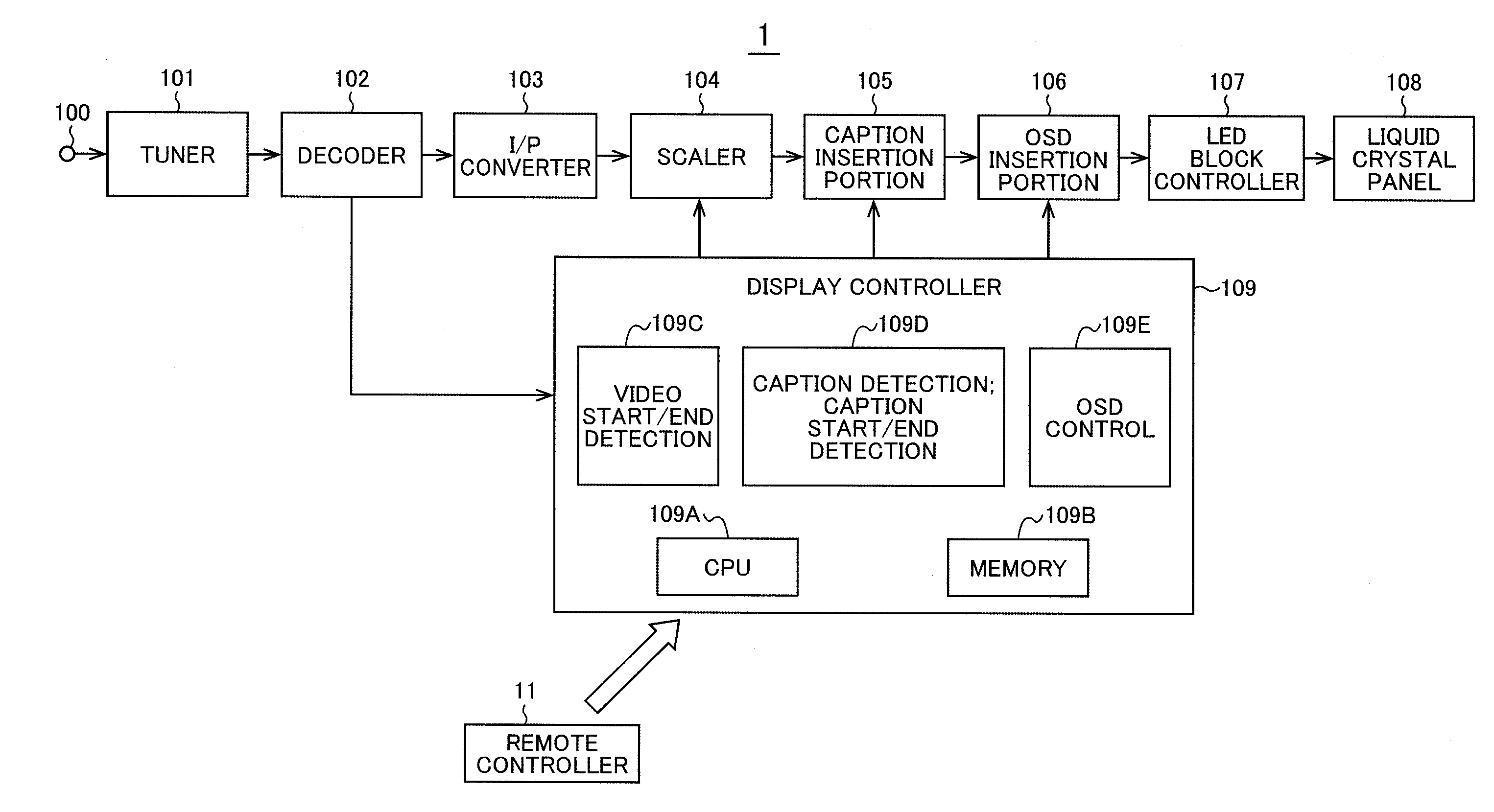
[0039]FIG. 1 is a block diagram of a video display device 1 according to an embodiment of the present invention. Firstly, the operation of the whole video display device will be described by using FIG. 1.

[0040]To a tuner (also referred to as a receiving portion) 101 through an input terminal 100, there are supplied radio signals of a television broadcast received by a receiving antenna (not shown) external or internal to the video display device 1. The tuner 101 extracts the radio signal of a channel designated by a user from the supplied radio signals, and converts the frequency of the radio signal into a predetermined band, and then demodulates the signal subjected to modulation for transmission on the broadcasting station side to supply the demodulated signal, as a baseband band signal, to a decoder (also referred to as a received signal processor) 102.

[0041]The...


PUM


Abstract

A video display device is provided with a backlight for projecting light onto a display panel composed of plural backlight blocks two-dimensionally arranged, for controlling the intensity of light for each of the backlight blocks by local dimming control. In the video display device, video, such as letterbox video, having a black blank portion and a video portion is displayed so as to nearly align a boundary between the video portion and the blank portion with a boundary between the backlight blocks. Also, reduced display is performed using only a portion of the backlight blocks in both horizontal and vertical directions while nearly aligning the boundary between the video portion and the blank portion with the boundary between the backlight blocks.

Description

INCORPORATION BY REFERENCE[0001]This application relates to and claims priority from Japanese Patent Application No. 2010-116443 filed on May 20, 2010, the entire disclosure of which is incorporated herein by reference.BACKGROUND OF THE INVENTION[0002]1. Field of the Invention[0003]The present invention relates to a video display device, and more particularly, to a low-power-consumption video display device.[0004]2. Description of the Related Art[0005]In video display devices such as liquid crystal display devices, there have been developed technologies for reducing power consumption in response to the current trend toward energy conservation.[0006]Japanese Patent Application Laid-Open No. 2003-156728 discloses a technique for reducing the power consumption of a backlight unit when the output voltage of a battery is reduced in a liquid crystal display device. Also, Japanese Patent Application Laid-Open No. 2001-21863 discloses a technique for reducing the power consumption of a back...

Claims


Application Information

Patent Timeline
IPC IPC(8): G09G3/36G09G5/02
CPCG09G3/3426G09G2320/0646H04N5/44591H04N21/4886H04N21/431H04N21/4854H04N7/0122H04N21/4316H04N21/47
Inventor KIMURA, KATSUNOBUMASUOKA, NOBUO
Owner HITACHI CONSUMER ELECTRONICS CORP
Why Eureka
Try Eureka