Coaxial support structure for towed marine seismic source arrays

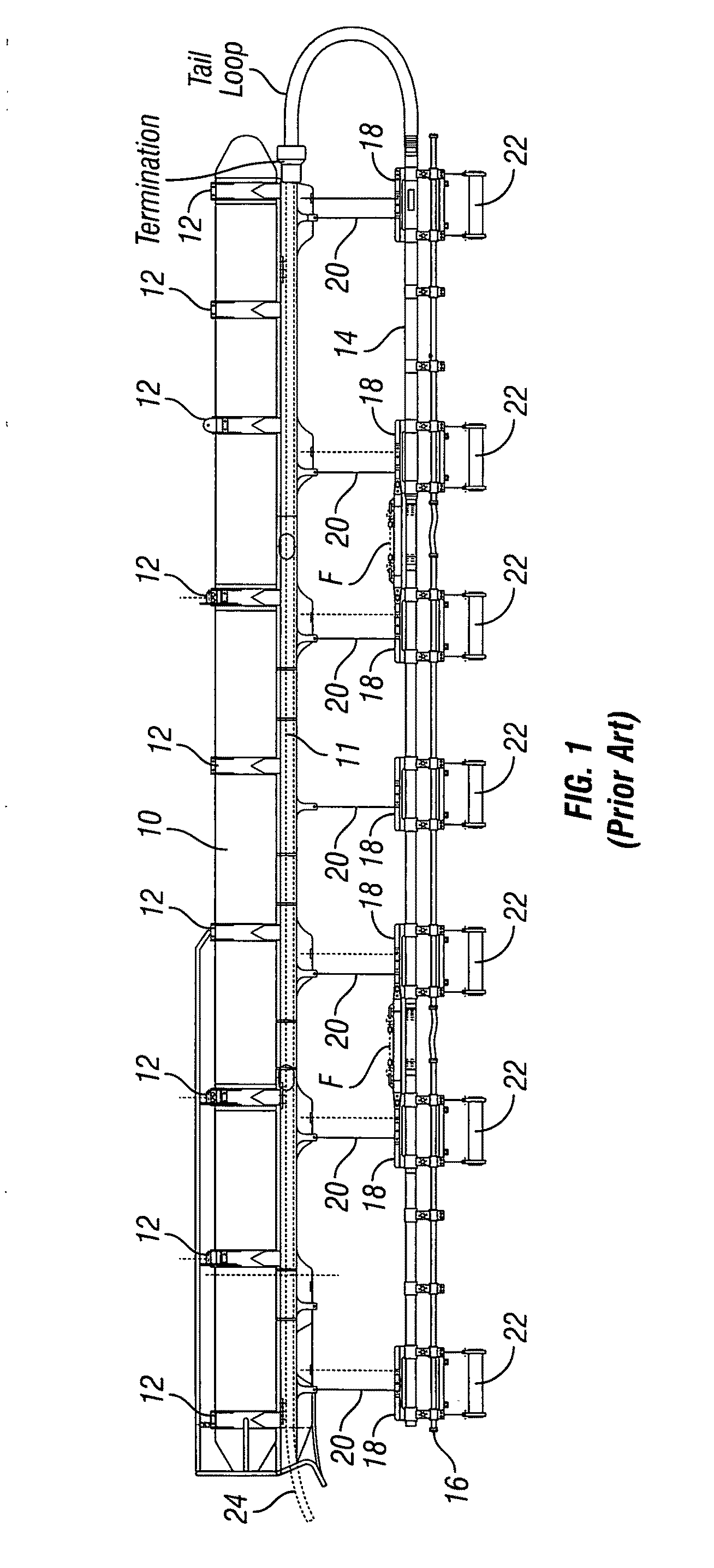
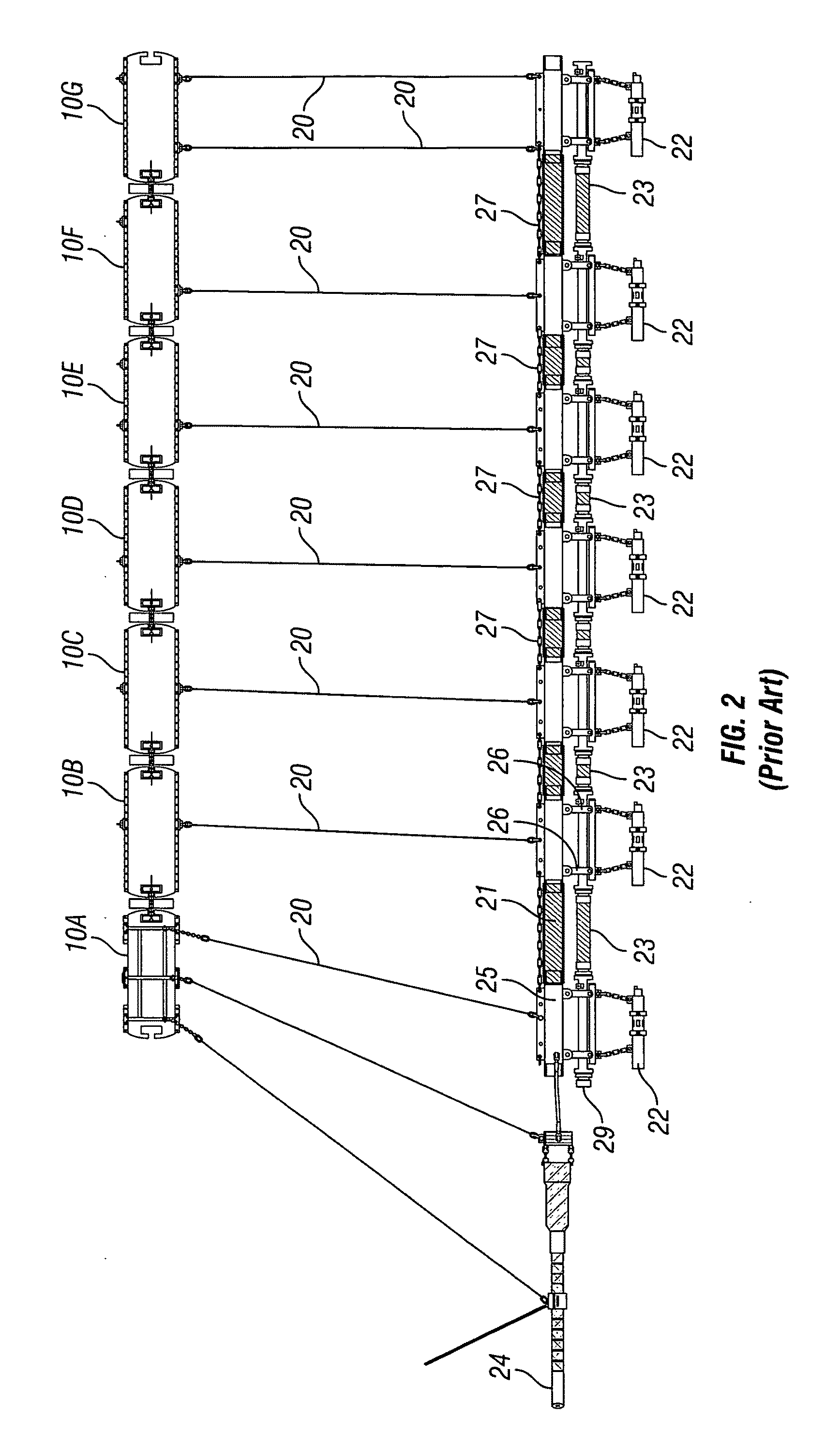
a technology of supporting structure and source array, which is applied in seismology, seismology, instruments, etc., can solve the problems of bending fatigue at the connection, fatigue in the stiff section components themselves, and the arrangement in fig. 2 is also susceptible to bending fatigue and failur

Inactive Publication Date: 2011-11-24
PGS GEOPHYSICAL AS
View PDF4 Cites 14 Cited by
  • Summary
  • Abstract
  • Description
  • Claims
  • Application Information

AI Technical Summary

Problems solved by technology

One of the difficulties with the foregoing arrangement is bend fatigue at the connections between the flexural sections F and the adjacent stiff sec

Method used


Image

  • Coaxial support structure for towed marine seismic source arrays
  • Coaxial support structure for towed marine seismic source arrays
  • Coaxial support structure for towed marine seismic source arrays

Examples


Embodiment Construction

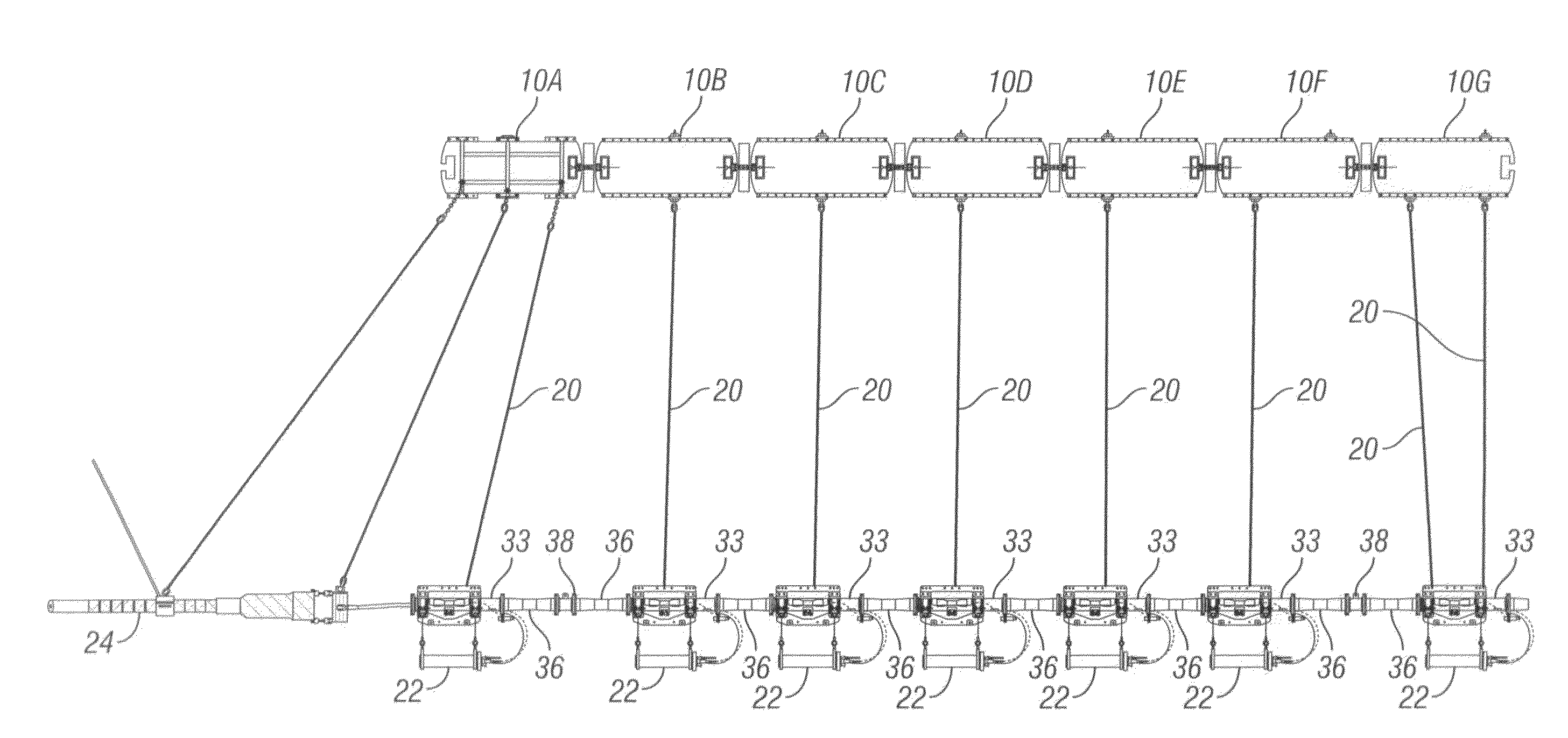
[0022]An example of a section of a towed marine source array with support structure according to the invention is shown in FIG. 3. The section shown in FIG. 3 includes three rigid sections or “gun boxes” each of which may include a rigid pipe section 33. The rigid pipe section33 includes a coupling 34 at each end The coupling 34 may be, for example any type of flange, including bolt-through annular rings, or rings that may be coupled to a mating flange using external clamps. Each rigid pipe section 33 includes a bracket 32 coupled to the exterior of the pipe section 33, such as by clamps. The bracket 32 includes openings on an upper part thereof to affix depth ropes and deployment lines (e.g., as shown in FIG. 2). The bracket 32 includes openings on a lower part thereof for cables or chains 30 to suspend a seismic energy source 22 (e.g., air gun) from the bracket 32. The pipe section 33 and affixed bracket 32 will be shown in more detail and described with reference to FIG. 8. The i...


PUM


Abstract

A seismic source array includes at least one float. A plurality of rigid conduit sections each includes a bracket for suspension from the float at a selected depth in a body of water and configured to suspend a seismic energy source therefrom. At least one bend strain relief is coupled between adjacent rigid conduit sections. Each bend strain relief includes a coupling at each longitudinal end. Each bend strain relief includes woven fiber molded into flexible plastic for transmitting axial loading while absorbing bending and torsional stress. A seismic energy source is suspended from each bracket. Lines for operating the seismic energy sources pass through the rigid conduit sections and the at least one bending strain relief.

Description

CROSS-REFERENCE TO RELATED APPLICATIONS[0001]Not applicable.STATEMENT REGARDING FEDERALLY SPONSORED RESEARCH OR DEVELOPMENT Not applicable.BACKGROUND OF THE INVENTION[0002]1. Field of the Invention[0003]The invention relates generally to the field of marine seismic surveying. More specifically, the invention relates to support structures for towed marine seismic source arrays.[0004]2. Background Art[0005]Marine seismic surveying is typically performed by towing one or more arrays of seismic energy sources behind a survey vessel. A plurality of seismic sensor cables can also be towed by the survey vessel at laterally spaced apart positions with respect to the center line of the survey vessel.[0006]The source arrays are coupled to the survey vessel by an “umbilical cable” which provides axial strength to tow the source arrays, electrical signal conductors to actuate the individual sources and, when the seismic sources are air guns, compressed air lines to charge the guns between actua...

Claims


Application Information

Patent Timeline
IPC IPC(8): G01V1/38
CPCG01V1/3808G01V1/04G01V1/38G01V1/137
Inventor PAULL, WAYNE RUSSELLELVESTAD, KARL PETTER
Owner PGS GEOPHYSICAL AS
Why Eureka
Try Eureka