Fuel cell and method of manufacturing the same

a fuel cell and cell technology, applied in the field of fuel cells, can solve the problems of degradation of the cell, rapid increase of the cell temperature, etc., and achieve the effects of improving the wettability between the surface of the unit cell and the filler-metal used in the brazing process, increasing the fixing and sealing ability, and high sealing ability

Inactive Publication Date: 2011-11-24
SAMSUNG SDI CO LTD
View PDF3 Cites 11 Cited by
  • Summary
  • Abstract
  • Description
  • Claims
  • Application Information

AI Technical Summary

Benefits of technology

[0009]Aspects of embodiments of the present invention are directed toward a fuel cell and a method of manufacturing the same capable of improving the fixing and sealing ability between a unit cell and a cell cap or between a unit cell and a cell fixing member.
[0023]As described above, according to embodiments of the present invention, a heat treating process for effective fixing and sealing between a unit cell and a cell cap or cell fixing member is performed in the process of manufacturing the unit cell, so that an additional heat treating process is not required in a brazing process.
[0024]Also, the wettability between a surface of the unit cell and filler-metal used in the brazing process is improved using a welding portion, thereby increasing the fixing and sealing ability between the unit cell and a cell fixing member or between the unit cell and the cell cap. As a high sealing ability is secured, it can be expected that the lifetime of the fuel cell will be extended.

Problems solved by technology

In this case, when cracks are generated at a sealing portion due to the weakness of the sealing between a cell and a cell fixing member, both of the fuels are mixed and ignited at a high temperature.
As a result, the temperature of the cell is rapidly increased, and hence, the degradation of the cell is caused.

Method used


Image

  • Fuel cell and method of manufacturing the same
  • Fuel cell and method of manufacturing the same
  • Fuel cell and method of manufacturing the same

Examples


Embodiment Construction

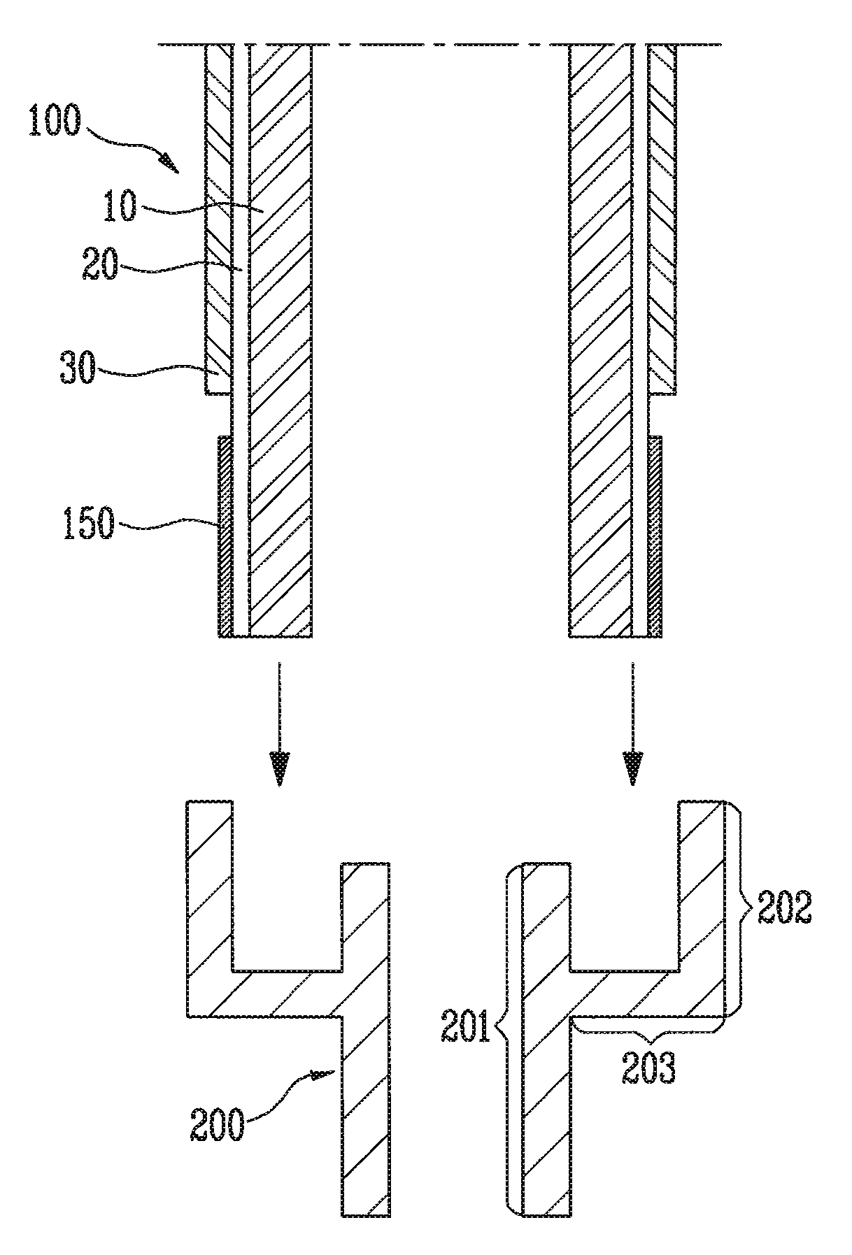
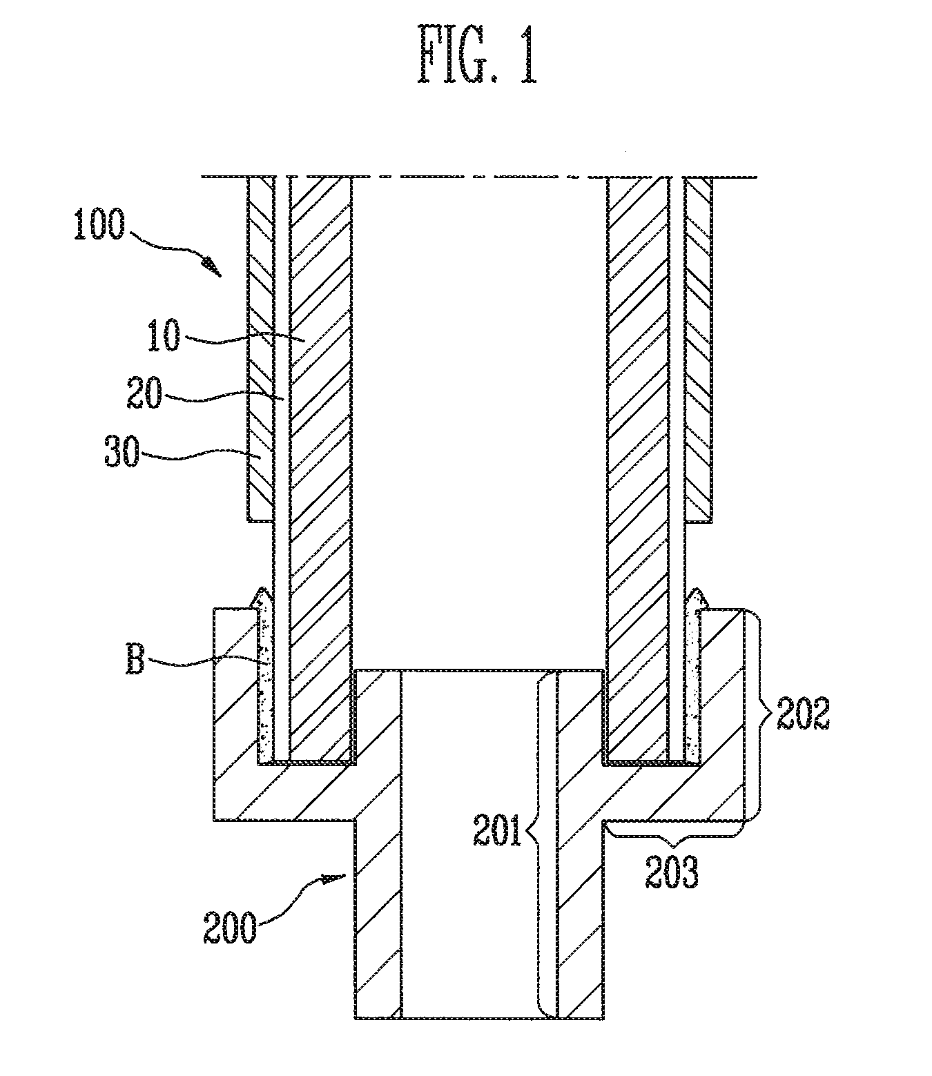
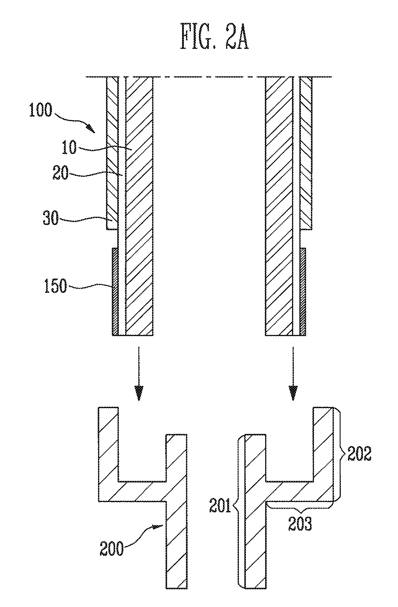
[0035]In the following detailed description, only certain exemplary embodiments of the present invention have been shown and described, simply by way of illustration. As those skilled in the art would realize, the described embodiments may be modified in various different ways, all without departing from the spirit or scope of the present invention. Accordingly, the drawings and description are to be regarded as illustrative in nature and not restrictive. In addition, when an element is referred to as being “on” another element, it can be directly on the another element or be indirectly on the another element with one or more intervening elements interposed therebetween. Also, when an element is referred to as being “connected to” another element, it can be directly connected to the another element or be indirectly connected to the another element with one or more intervening elements interposed therebetween. Hereinafter, like reference numerals refer to like elements.

[0036]In embod...


PUM

PropertyMeasurementUnit
temperatureaaaaaaaaaa
shapeaaaaaaaaaa
insertion depthaaaaaaaaaa

Abstract

A fuel cell includes a unit cell, a cell fixing member and a welding portion. The unit cell includes a first electrode layer, an electrolyte layer surrounding the first electrode layer, a second electrode layer surrounding the electrolyte layer while exposing an end portion of the electrolyte layer, and a coating layer formed by coating a mixture of ceramic and metal on the exposed end portion of the electrolyte layer. The cell fixing member includes a flow tube inserted into the unit cell, a fixing tube provided to an outside of the flow tube, and a connecting portion connecting the fixing tube and the flow tube to each other and to restrict an insertion depth of the electrolyte layer and the first electrode layer. The welding portion fixes and seals the coating layer and the inner circumferential surface of the fixing tube to each other.

Description

CROSS-REFERENCE TO RELATED APPLICATION[0001]This application claims priority to and the benefit of Korean Patent Application No. 10-2010-0046934, filed on May 19, 2010, in the Korean Intellectual Property Office, the entire content of which is incorporated herein by reference.BACKGROUND[0002]1. Field[0003]The following description relates to a fuel cell and a method of manufacturing the same, in which an effective brazing process can be performed between a unit cell and a cell fixing member such as a cell cap or cell connector.[0004]2. Description of the Related Art[0005]A fuel cell is a cell that converts chemical energy generated by oxidation into electric energy. The fuel cell is an eco-friendly technology that generates electric energy from materials such as oxygen and hydrogen, which are abundant on the Earth. In the fuel cell, an electrochemical reaction is performed as an inverse reaction of the electrolysis of water by respectively supplying oxygen and fuel gas to a cathode ...

Claims


Application Information

Patent Timeline
Patent Type & Authority Applications(United States)
IPC IPC(8): H01M2/08B05D5/12C25D7/00
CPCC23C18/1216C23C18/1225C25D5/12H01M8/0252H01M8/028Y02E60/525H01M8/1206H01M8/243H01M8/2485Y02E60/521H01M8/0286H01M8/1231Y02E60/50Y02P70/50B05D1/18H01M8/02H01M8/04H01M8/12H01M8/0271
Inventor SUH, JUN-WONKWEON, HO-JIN
Owner SAMSUNG SDI CO LTD
Why Eureka
Try Eureka