Intraocular Lens Insertion Device

a technology of insertion device and lens, which is applied in the field of intraocular lens insertion device, can solve the problems of rear supporting portion to be stretched, surgery trouble, etc., and achieve the effect of reducing the possibility of reoperation

Active Publication Date: 2011-11-24
HOYA CORP
View PDF3 Cites 63 Cited by
  • Summary
  • Abstract
  • Description
  • Claims
  • Application Information

AI Technical Summary

Benefits of technology

[0024]According to the present invention, the first abutting portion provided on the slider serves to push up the supporting portion arranged on the rear side with respect to the lens advancement axis, thereby allowing the motion

Problems solved by technology

However, this type of intraocular lens insertion device may cause a supporting portion (referred to as a rear supporting portion, hereunder) arranged on a rear side with respect to a lens advancement axis to slip in between a plunger for pushing out the intraocular lens and a passage inner wall surface of the insertion device, or be tangled with the corresponding plunger, during a process of moving the intraocular lens.
These problems are particularly noticeable with soft intraocular lenses employing thin filamentary members as supporting portions and intraocular lenses

Method used


Image

  • Intraocular Lens Insertion Device
  • Intraocular Lens Insertion Device
  • Intraocular Lens Insertion Device

Examples


first embodiment

1. FIRST EMBODIMENT

[0044](1) Basic Structure

[0045]An embodiment of the present invention is described hereunder in detail and with reference to the accompanying drawings.

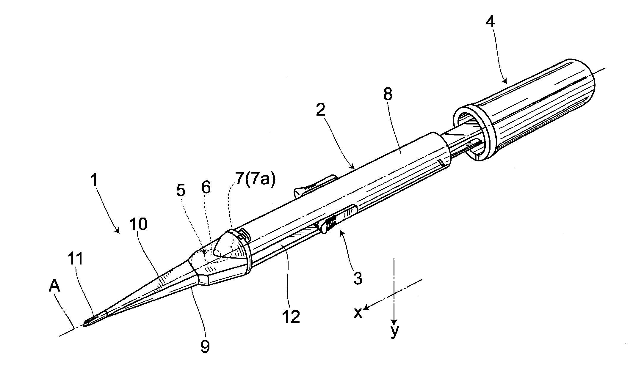
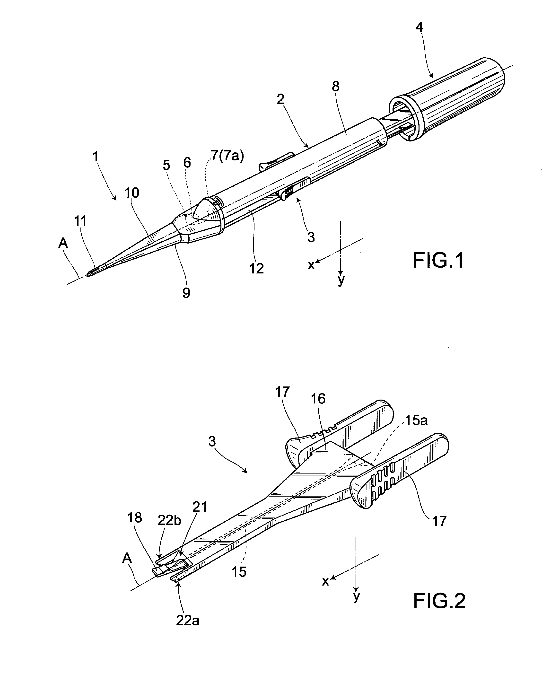
[0046]An intraocular lens insertion device 1 shown in FIG. 1 comprises a main body 2, and a slider 3 and a plunger 4 that are attached to the main body 2. The intraocular lens insertion device 1 is of a preset type in which an intraocular lens 5 is placed inside the main body 2 in advance. Here, the intraocular lens 5 includes an optical part 6 and a pair of supporting portions 7 provided on an outer edge of the optical part 6. As the supporting portions 7, there can be employed various types of members including, for example, members of a thin strip type.

[0047]In the following descriptions, an axis extending through the center of the intraocular lens 5 moving inside the main body 2 is referred to as a lens advancement axis A. Further, a direction to which the intraocular lens 5 moves is referred to as an “advanceme...

second embodiment

2. SECOND EMBODIMENT

[0071]A second embodiment of the present invention is described hereunder with reference to the accompanying drawings. Here, the second embodiment differs from the first embodiment only in the structure of the front end portion of the slider 3. Therefore, same symbols are used to describe the same members as those in the first embodiment, and the descriptions of the corresponding members are thus omitted for the sake of convenience.

[0072]According to a slider 30 shown in FIG. 9, at least 22a of second abutting portions 22a, 22b is configured to abut against an outer edge of a section of the optical part 6 between the connecting portion of the rear supporting portion 7a and the optical part 6, and the lens advancement axis A. Further, this slider 30 has a cutout hole 31 formed on a side surface thereof, such cutout hole 31 allowing the rear supporting portion 7a to be inserted therethrough inwardly from the outside.

[0073]According to the present embodiment having ...

third embodiment

3. THIRD EMBODIMENT

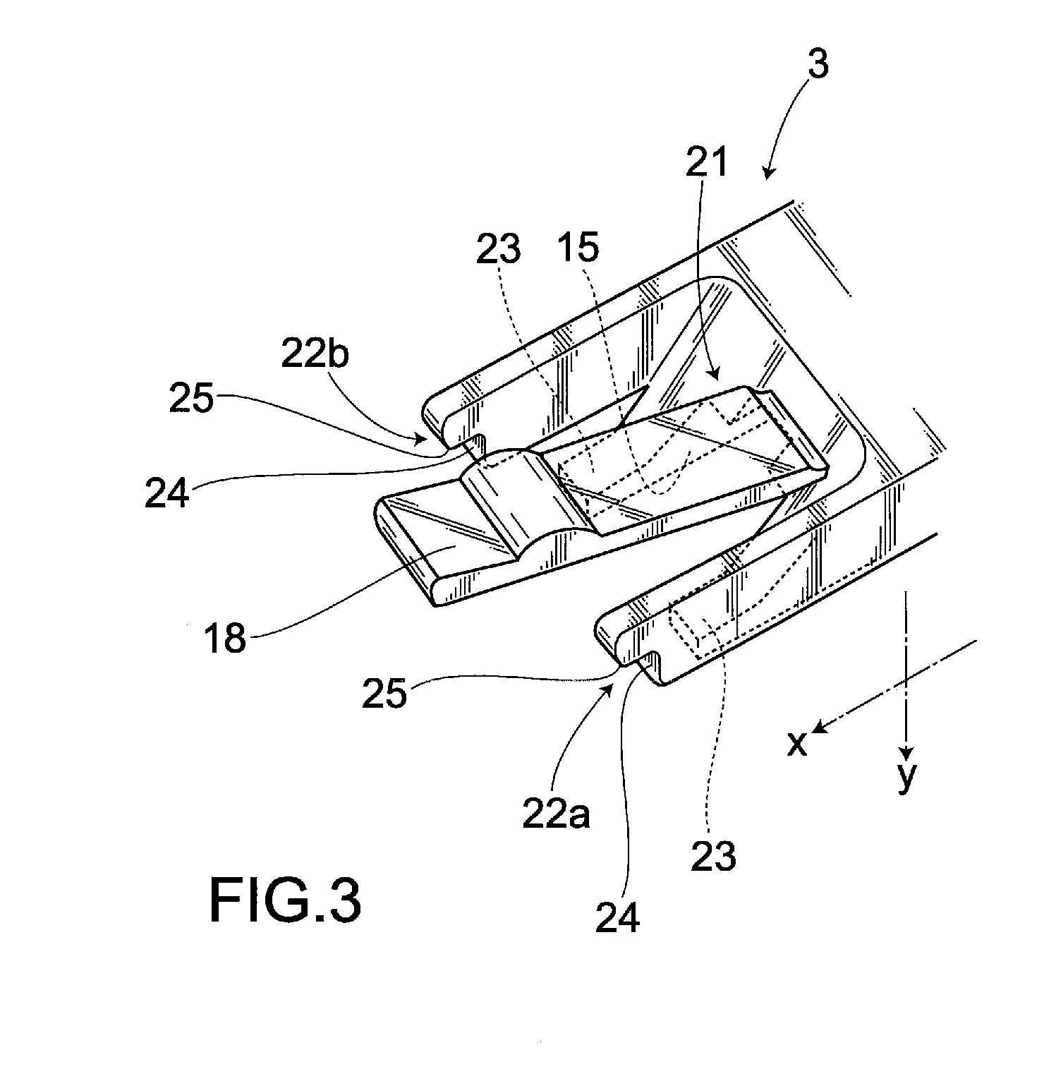
[0078]As shown in FIG. 13, a slider 40 of the present embodiment includes a first abutting portion 21, second abutting portions 22a, 22b and a guiding portion 41 for guiding the optical part 6 to the second abutting portion 22b. The second abutting portion 22b is provided on a location opposite to the connecting portion of the rear supporting portion 7a and the optical part 6, and is configured to be able to abut against the optical part 6 or the outer edge thereof. Further, the second abutting portion 22b has an x-direction abutting surface 24 and a y-direction abutting surface 25. In contrast, the second abutting portion 22a only has the x-direction abutting surface 24.

[0079]Here, the y-direction abutting surface 25 of the second abutting portion 22b may be arranged substantially on the same plane as restriction portions 23, or beyond the restriction portions 23 in the direction y. According to the present embodiment, the y-direction abutting surface 25 is arran...


PUM


Abstract

There is provided an intraocular lens insertion device capable of appropriately regulating the motion of a rear supporting portion during a process of moving an intraocular lens, and reducing the possibility of reoperation being required after the intraocular lens is inserted into an eye. An intraocular lens insertion device 1 comprises a main body 2, and a slider 3 and a plunger 4 that are attached to the main body 2. Further, the intraocular lens insertion device 1 is of a preset type in which an intraocular lens 5 is placed inside the main body 2 in advance. The slider 3 includes a first abutting portion 21 for pushing up a supporting portion 7 (rear supporting portion 7a) arranged on a rear side of an optical part 6 with respect to a lens advancement axis A, and second abutting portions 22a, 22b abutting against an outer edge of a rear portion of the optical part 6.

Description

TECHNICAL FIELD[0001]The present invention relates to an intraocular lens insertion device for inserting an intraocular lens into an eyeball as a substitute of a crystalline lens exenterated through cataract surgery.BACKGROUND ART[0002]Cataract surgery often involves removing an opacified crystalline lens through phacoemulsification (PEA), and implanting an intraocular lens after the crystalline lens has been removed. Intraocular lenses include hard intraocular lenses whose optical parts are made of hard materials such as PMMA or the like, and soft intraocular lenses whose optical parts are made of soft materials such as silicon elastomer, soft acrylic, hydrogel or the like.[0003]When inserting a hard intraocular lens, there has to be formed on the cornea or the sclera an incision substantially as wide as the diameter of the optical part of the corresponding hard intraocular lens. In contrast, a soft intraocular lens can be inserted through an incision smaller than the diameter of t...

Claims


Application Information

Patent Timeline
IPC IPC(8): A61F9/007
CPCA61F2/167A61F2/1672
Inventor KUDO, KAZUNORINODA, MASAHIRO
Owner HOYA CORP
Why Eureka
Try Eureka