[0010]It is an object of the invention to provide a laundry treatment apparatus having a heat pump system and a method of operating a laundry treatment apparatus, in which the time for the heat pump system to come to an elevated efficiency is shortened without the need for additional elements.
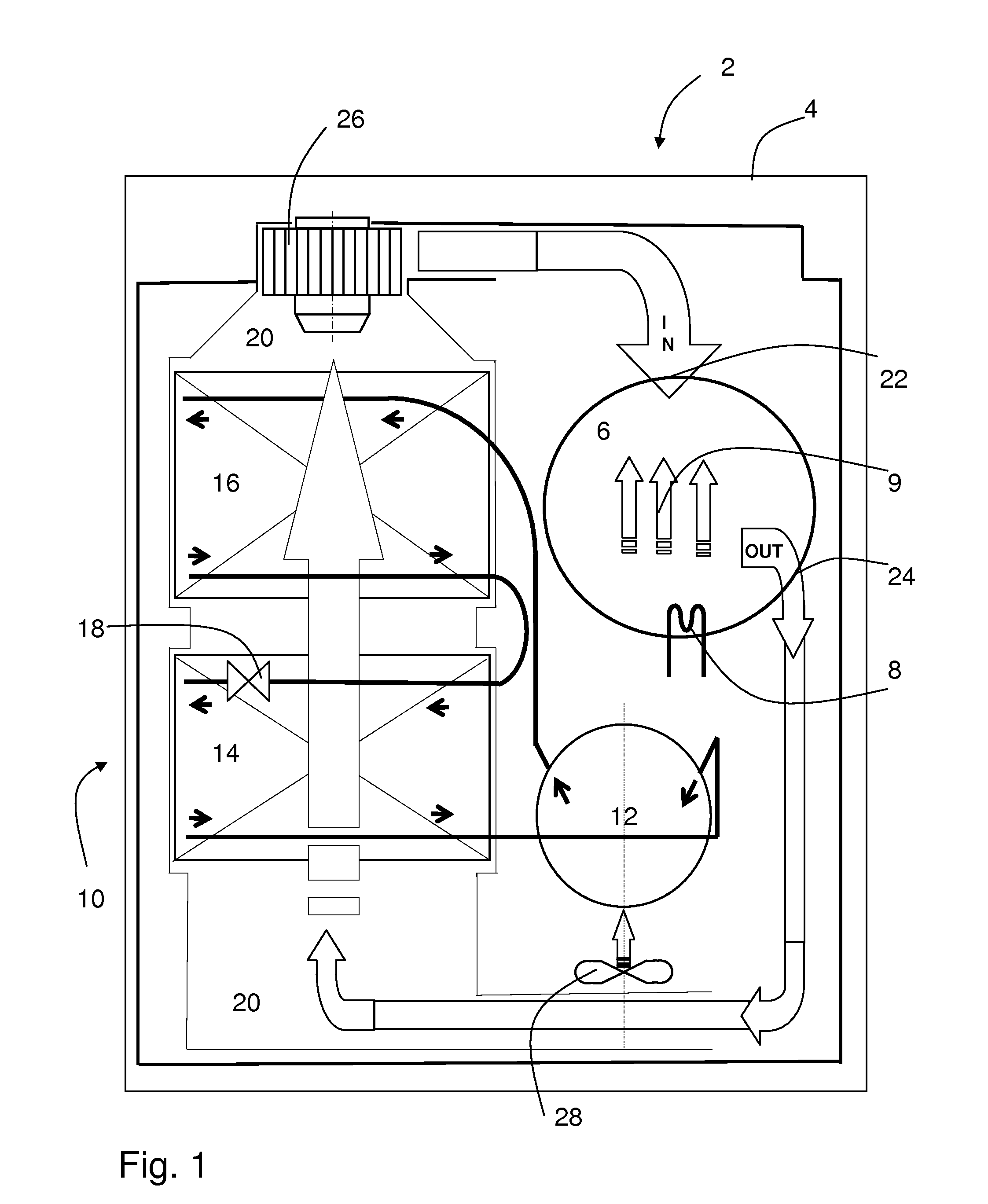
[0016]In an embodiment the steam is generated by the steam generator and supplied to the air circulation channel and / or the storing compartment for a predefined period since or after starting the operation of the heat pump system and then after the predefined period the
steam generation and supply is stopped. By this overlap of the operation of the heat pump system and the steam generator the intermediate effect of additional
energy consumption by the steam generator is limited and in total the result of this additional energy consumption and humidification of the laundry is more than counterbalanced by the acceleration of the equilibration process for the heat pump system to come to high efficiency in the
drying cycle.
[0021]Alternatively or additionally one or more of the parameters are the pressure and / or temperature of the
working fluid in the
evaporator (for example measured at the inlet / outlet thereof), the condenser and / or the compressor. For example, the pressure within the evaporator is measured which indicates the pressure of the
working fluid (or
cooling fluid), wherein a sufficient pressure limit has to be achieved before the compressor and thus the heat pump system can operate efficiently.
[0031]According to a preferred embodiment the
control unit of the laundry treatment apparatus is adapted to operate the heat pump system and the steam generator at the same time at least for one or a plurality of overlapping periods, preferably during the
initial phase of the operation of the heat pump system such that the evaporator is heated in the start-up phase of the heat pump system. Thereby the
working temperature of the evaporator and the
coolant liquid therein is increased to increase the
evaporation of the
coolant liquid within the evaporator. This increases the efficiency of the compressor by providing
coolant liquid vapour to be compressed.
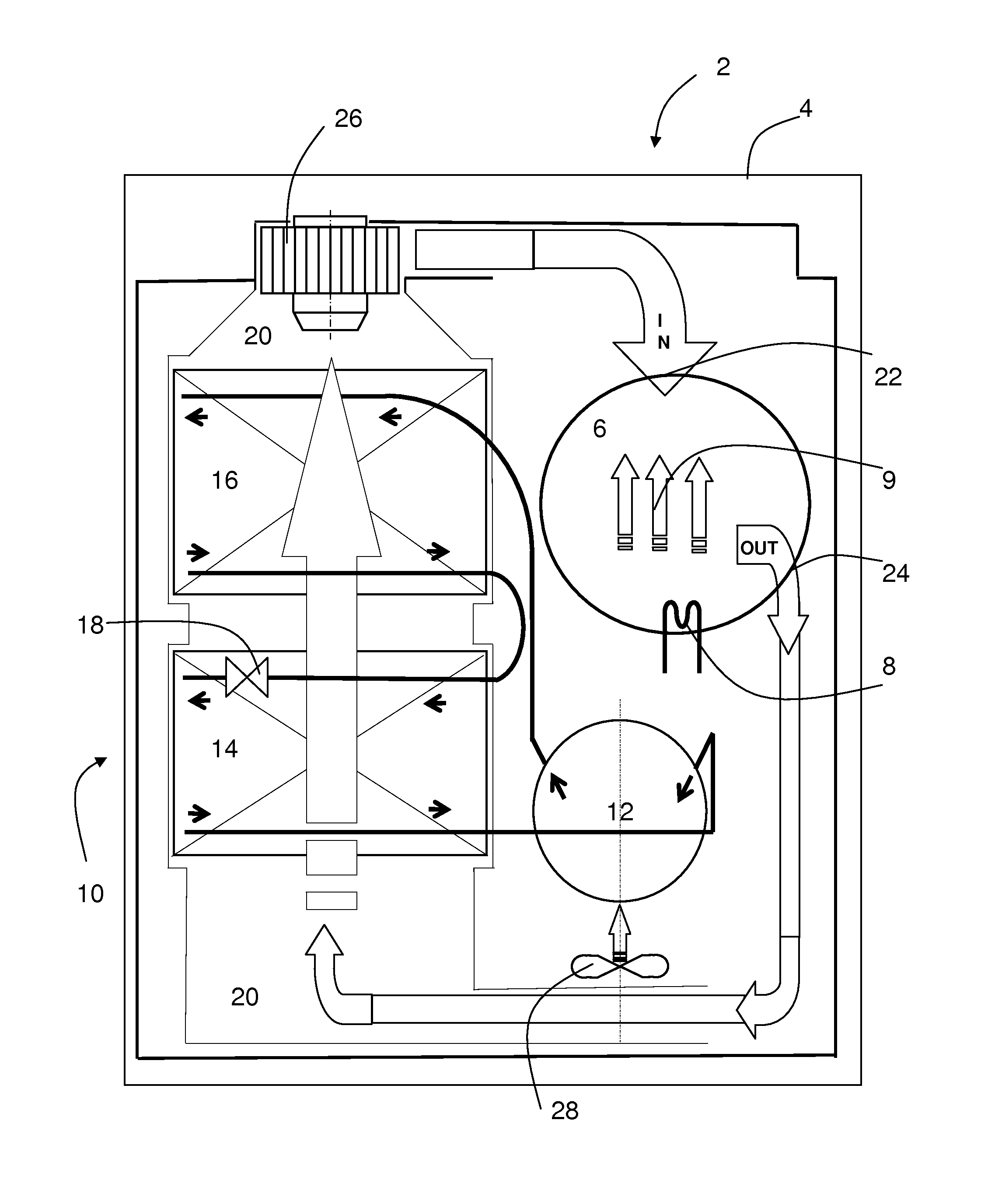
[0034]According to an embodiment, the laundry treatment apparatus has a storing compartment, in particular a rotatable drum, that is enclosed by a tub or container and a
sump arranged in the tub below the storing compartment (e.g. rotatable drum). A
heating element arranged in or at the
sump is configured to heat up water contained in the
sump to generate steam and to supply it to the storing compartment. Preferably, the storing compartment has a plurality of openings connecting its interior and the outer volume within the tub, so that the steam can permeate into the storing compartment for laundry
processing.
[0035]According to a preferred embodiment the blower has an
operation mode with reduced or zero air conveying power. For example, an
operation mode in which the blower is de-energized or stopped or in which the power provided to the blower is reduced. Then the
control unit of the treatment apparatus is adapted to control the steam generator to generate and supply steam while the blower is de-energized or operating with a reduced air amount conveying power at least partially during the
initial phase of operating the heat pump system. In case of reduced air conveying, the hot steam is first provided to the evaporator to heat up the evaporator and the reduced air circulation speed causes the heat
exchange time (dwell time) between steam and evaporator to be extended. In case of de-energizing the blower the steam can diffuse to the evaporator and deposit the
heat energy there. In particular, when the evaporator is arranged at an upper level within the body of the treatment apparatus, the hot steam will ascend and collect at the evaporator to heat it up. This
chimney effect is improved when the laundry treatment apparatus is configured such that the evaporator is arranged above an inlet area or
steam generation area for supplying the steam into the storing compartment and / or air circulation channel.

