Microwave heating apparatus

Inactive Publication Date: 2011-12-01
HITACHI LTD
View PDF4 Cites 6 Cited by
  • Summary
  • Abstract
  • Description
  • Claims
  • Application Information

AI Technical Summary

Benefits of technology

[0023]In accordance with the present invention, there can be provided a microwave heating apparatus which can have a very large throughput by

Problems solved by technology

More specifically, with respect to a dielectric material, use of microwaves has a limit in penetration depth.
In this method, however, it is undesirably considered in some cases that the microwaves can be absorbed by only the surface of the heating target material but cannot penetrate into the interior of the material, thus resulting in uneven heating (,though it is acceptably considered in some cases that, when a target material is merely heated, even somewhat uneven heating can involve less problem).
However, uneveness in a microwave absorption distribution can cause generation of irregular products, thus undesirably leading to quality deterioration of the products.
However, the heating method has a problem that it is difficult for a magnetron widely being used for microw

Method used


Image

  • Microwave heating apparatus
  • Microwave heating apparatus
  • Microwave heating apparatus

Examples


embodiment 1

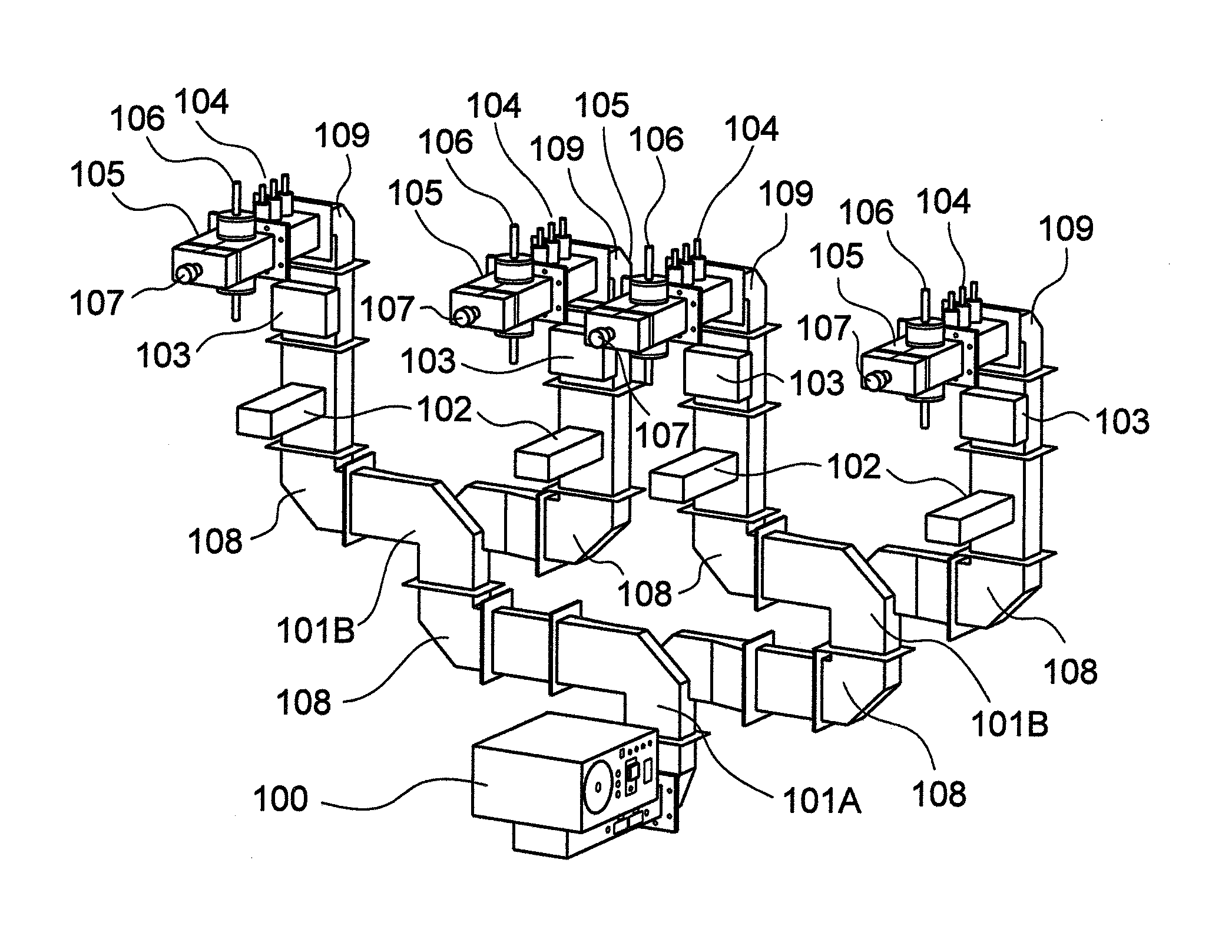
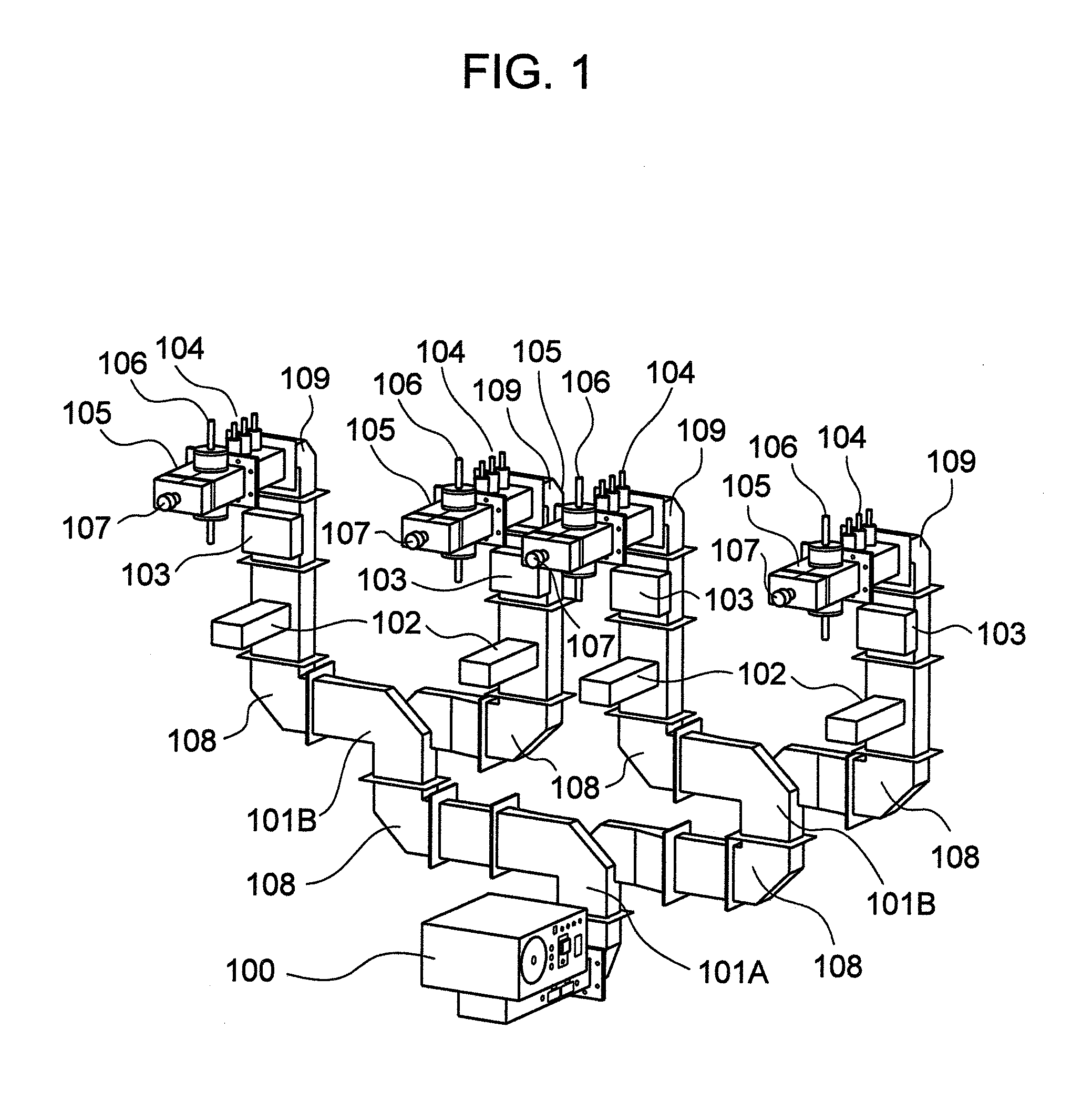
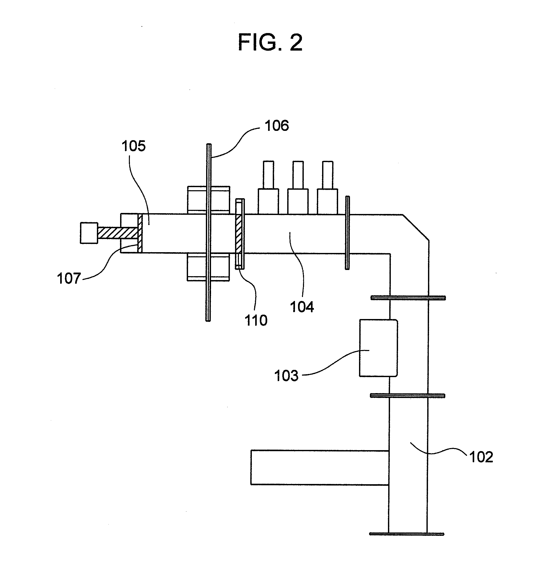
[0040]A first embodiment of the present invention will be explained in connection of a microwave heating apparatus shown in FIGS. 1 and 2.

[0041]FIG. 1 is a perspective view of a microwave heating section in the present embodiment.

[0042]FIG. 2 is a side view of the microwave heating section in the present embodiment.

[0043]In FIG. 1, the microwave heating section includes a microwave generator 100 for generating microwaves, and a branch waveguide 101A for branching the microwaves into two waves is connected to the microwave generator 100. A branch waveguide 101B is used to branch the branched microwaves further into two microwaves. An isolator 102 is provided to absorb reflected waves. A power monitor 103 is used to measure magnitudes of incident and reflected waves. A tuner 104 is provided to adjust an impedance in the apparatus.

[0044]A reaction tube 106, which functions to make a heating target material to flow into the interior thereof, is installed with an applicator 105. A H-plan...

embodiment 2

[0077]Explanation will then be made as to a second embodiment with reference to FIGS. 1 and 5.

[0078]FIG. 5 is a perspective view of a microwave heating apparatus in accordance with a second embodiment of the present invention.

[0079]In FIG. 5, the present embodiment includes, in addition to the microwave heating section of FIG. 1, supply fluid pumps 111a to 111e for supplying a plurality of materials and mixers 114a to 114d for mixing two fluids.

[0080]The microwave heating apparatus in accordance with the present embodiment can execute a plurality of heating processes in a time series manner. For example, first and second materials are supplied by the supply fluid pumps 111a and 111b to the mixer 114a for mixture. The mixed fluid is caused to flow into a reaction tube 106a, and is irradiated with microwaves, thus carrying out a heating process. The heated reaction fluid is caused to flow further into another mixer 114b and mixed therein with a third material supplied by the supply fl...

embodiment 3

[0088]A third embodiment of the present invention will then be explained with reference to FIG. 8.

[0089]FIG. 8 is a perspective view of a microwave heating apparatus in accordance with a third embodiment of the present invention.

[0090]In FIG. 8, the microwave heating apparatus of the present embodiment includes a microwave generator 100 for generating microwaves, isolators 102 for absorbing reflected waves, power monitors 103 for measuring magnitudes of incident and reflected waves, tuners 104 for adjusting an impedance in the apparatus, reaction tubes 106 through which heating target materials flow, and applicators 105 provided to install the reaction tubes 106. In the present embodiment, when the reaction fields are arranged radially from the microwave generator 100 as its center, the reaction fields can be heated simultaneously, parallelly and independently.

[0091]Although the present embodiment has been explained in connection with the example where the four reaction fields are r...


PUM


Abstract

A microwave heating apparatus in which microwaves from a single microwave generator is branched to a plurality of reaction tubes, a heating target material is irradiated with the microwaves while being continuously supplied into respective reaction fields, the reaction fields is heated and controlled simultaneously, parallelly and independently while eliminating the influence of reflected waves generated in the other reaction fields, and a very high throughput is obtained. In the apparatus, branch waveguides for branching microwaves generated from a microwave generator into N branch waves, N being an natural number, are provided, isolators for absorbing reflected waves generated in the reaction fields are provided between the branch waveguides and applicators, power monitors for measuring magnitudes of incident and reflected waves are provided between the isolators and the applicators, and tuners for adjusting impedances in waveguides are provided between the power monitors and the applicators.

Description

BACKGROUND OF THE INVENTION[0001]The present invention relates to a microwave heating apparatus which heats a chemical liquid with microwaves.[0002]Heating with microwaves is widely employed currently for a home-use microwave oven, but the microwave heating is also used for industrial use. For example, the microwave heating is used for rubber cure or vulcanization, tea leave drying, food sterilization and so on. These years, the microwave heating starts being employed even for chemical synthesis process.[0003]Microwave heating in the chemical synthesis process, when compared with a conventional heating method by an external heating source, has been reported not only to be more increased or improved in reaction rate and other operational factors, but also to be more valid in microwave chemical reaction (refer to a book published from CMC Press and entitled “Microwave-assisted Chemical Process Technology”, page 10 to page 20 and page 119 to page 129, compiled under the supervision of ...

Claims


Application Information

Patent Timeline
IPC IPC(8): H05B6/70
CPCH05B6/701H05B6/806H05B6/76H05B6/705
Inventor MATSUZAWA, MITSUHIROTOGASHI, SHIGENORI
Owner HITACHI LTD
Why Eureka
Try Eureka