System and method of optical measurements for wellbore survey

a wellbore and optical measurement technology, applied in the field of optical measurements for wellbore surveys, can solve the problems of bha not being always at a constant temperature, affecting the lifetime, stability and output luminance of light sources, and affecting the performance of light sources

Inactive Publication Date: 2011-12-01
SCHLUMBERGER TECH CORP
View PDF11 Cites 30 Cited by
  • Summary
  • Abstract
  • Description
  • Claims
  • Application Information

AI Technical Summary

Benefits of technology

[0010]In aspects herein, the system may comprise a data transmitting unit for transmitting light modulated based on data generated in the optical measurement apparatus, via the light conveyable cable. Furthermore, the light output from the light source may include one or more wavelengths of near infrared. The one or more wavelengths may include at least one of a first wavelength of ap

Problems solved by technology

The operation in the wide temperature range impairs the performance such as lifetime, stability and output luminance of the light source.
For example, the continuous operation in the high temperature range degrades output luminance and lifetime of the light source.
In addition, in the wellbore the BHA cannot be always at a constant temperature.
So, these phase drifts are not acceptable.
In addition, it is difficult to control temperature of the light source disposed in wellbore under the ground, because a temperature control device such as a Peltier device can not function effectively due to high ambient temperature over 100° C. in environment around the light source in the wellbore.
In we

Method used


Image

  • System and method of optical measurements for wellbore survey
  • System and method of optical measurements for wellbore survey
  • System and method of optical measurements for wellbore survey

Examples


Embodiment Construction

[0019]Illustrative embodiments and aspects of the present disclosure are described below. In the interest of clarity, not all features of an actual implementation are described in the specification. It will of course be appreciated that in the development of any such actual embodiment, numerous implementation-specific decisions must be made to achieve the developers' specific goals, such as compliance with system-related and business-related constraints, which will vary from one implementation to another. Moreover, it will be appreciated that such development effort might be complex and time-consuming, but would nevertheless be a routine undertaking for those of ordinary skill in the art having benefit of the disclosure herein.

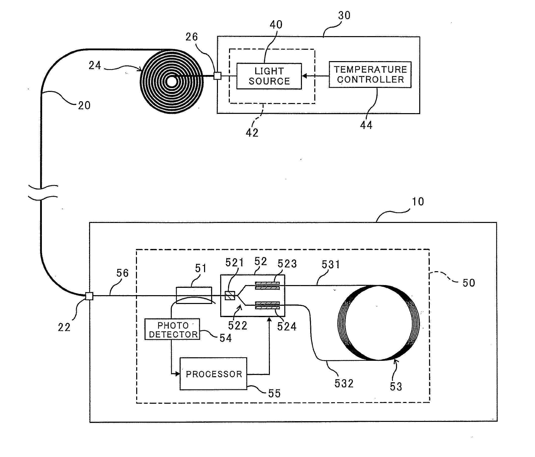
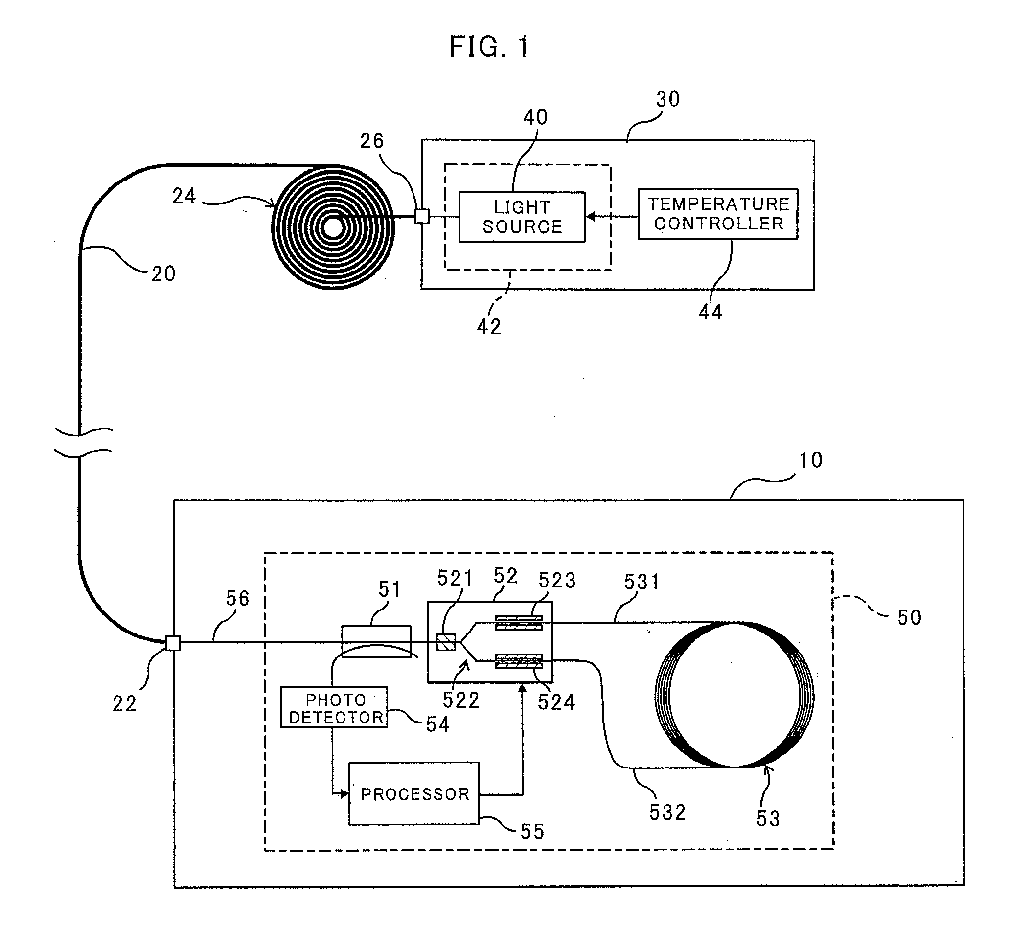
[0020]In one of exemplary applications of a System for wellbore survey using an optical measurement apparatus according to the disclosure herein, the system comprises a light source, a logging cable as a light conveyable cable including a optical fiber, and at...


PUM


Abstract

A system of optical measurements for wellbore survey comprises a light conveyable cable, an optical measurement apparatus optically coupled to one end of the light conveyable cable, and a light source optically coupled to another end of the light conveyable cable. The light source produces light used for optical measurements in the optical measurement apparatus.

Description

FIELD OF THE INVENTION[0001]The present invention relates generally to optical measurements for wellbore survey. More specifically, some aspects disclosed herein are directed to systems and method of optical measurements using light output from a light source for wellbore surveys such as wellbore trajectory measurements, azimuth measurements and navigation in boreholes.BACKGROUND OF THE INVENTION[0002]An optical measurement apparatus including a light source has been proposed for measurements of various parameters for wellbore surveys during WireLine (“WL”) logging operations, Logging-While-Drilling (“LWD”) operations and Measurement-While-Drilling (“MWD”) operations. For example, a continuous MWD survey apparatus including two fiber optic gyroscopes (“FOG”) together with three accelerometers is disclosed in U.S. Pat. No. 6,668,465 which is incorporated herein by reference in its entirety. One of the FOGs is sensitive to rotation about a tool spin axis of a bottom hole assembly (“BH...

Claims


Application Information

Patent Timeline
IPC IPC(8): G01V5/04
CPCG01V8/02
Inventor SATO, SHIGERUYAMATE, TSUTOMU
Owner SCHLUMBERGER TECH CORP
Why Eureka
Try Eureka