
Semiconductor chip and method for generating pulse edges, assigned synchronously to the movement of a mechanical part

a technology of semiconductors and mechanical parts, applied in the direction of converting sensor output, magnitude/direction of magnetic fields, measurement devices, etc., can solve the problem of inaccuracy in detection of maximum or minimum values

Active Publication Date: 2011-12-01
TDK MICRONAS GMBH
View PDF4 Cites 34 Cited by
  • Summary
  • Abstract
  • Description
  • Claims
  • Application Information

AI Technical Summary

Benefits of technology

[0006]It is therefore an object of the present invention to provide a method in which the pulse edges are synchronous as precisely as possible to the movement of the mechanical part. It is a further object to provide a semiconductor chip of the aforementioned type, which makes it possible to generate a signal having pulse edges, which is synchronous as precisely as possible to the modulation of a magnetic flux penetrating the magnetic field sensor.
[0008]In an advantageous manner, the reference values in process steps a) and b) can each be placed in a section of the measuring signal, in which the signal has a steep slope. Thus, for example, in the case of a sinusoidal or cosinusoidal measuring signal the reference value can be in the area of the zero-crossing of the measuring signal. Because the measuring signals have a phase shift relative to one another, pulse edges generated with the use of a first measuring signal can lie between pulse edges generated with the use of a second measuring signal. Therefore, a plurality of pulse edges synchronous to the movement of the mechanical part can be generated with great precision in a simple manner.

Problems solved by technology

The method has the disadvantage that the detection of the maximum or of the minimum is beset with inaccuracies.

Method used


Image

  • Semiconductor chip and method for generating pulse edges, assigned synchronously to the movement of a mechanical part
  • Semiconductor chip and method for generating pulse edges, assigned synchronously to the movement of a mechanical part
  • Semiconductor chip and method for generating pulse edges, assigned synchronously to the movement of a mechanical part

Examples


Embodiment Construction

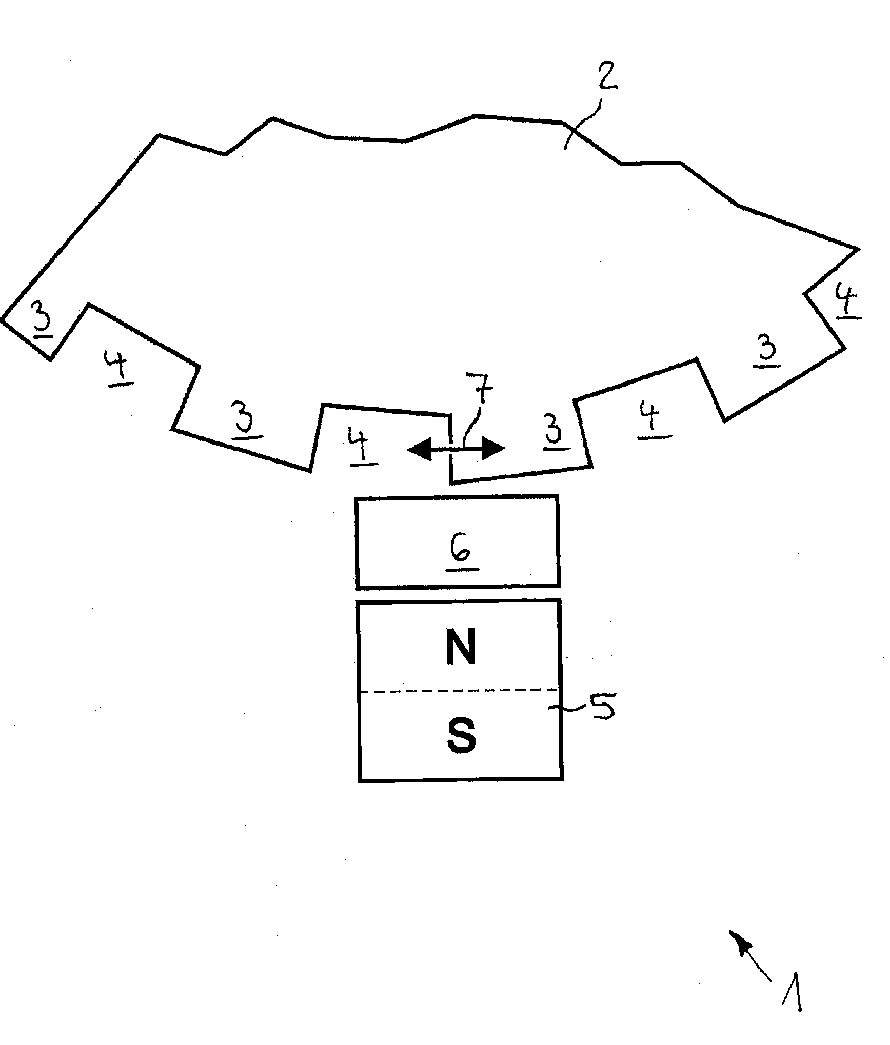
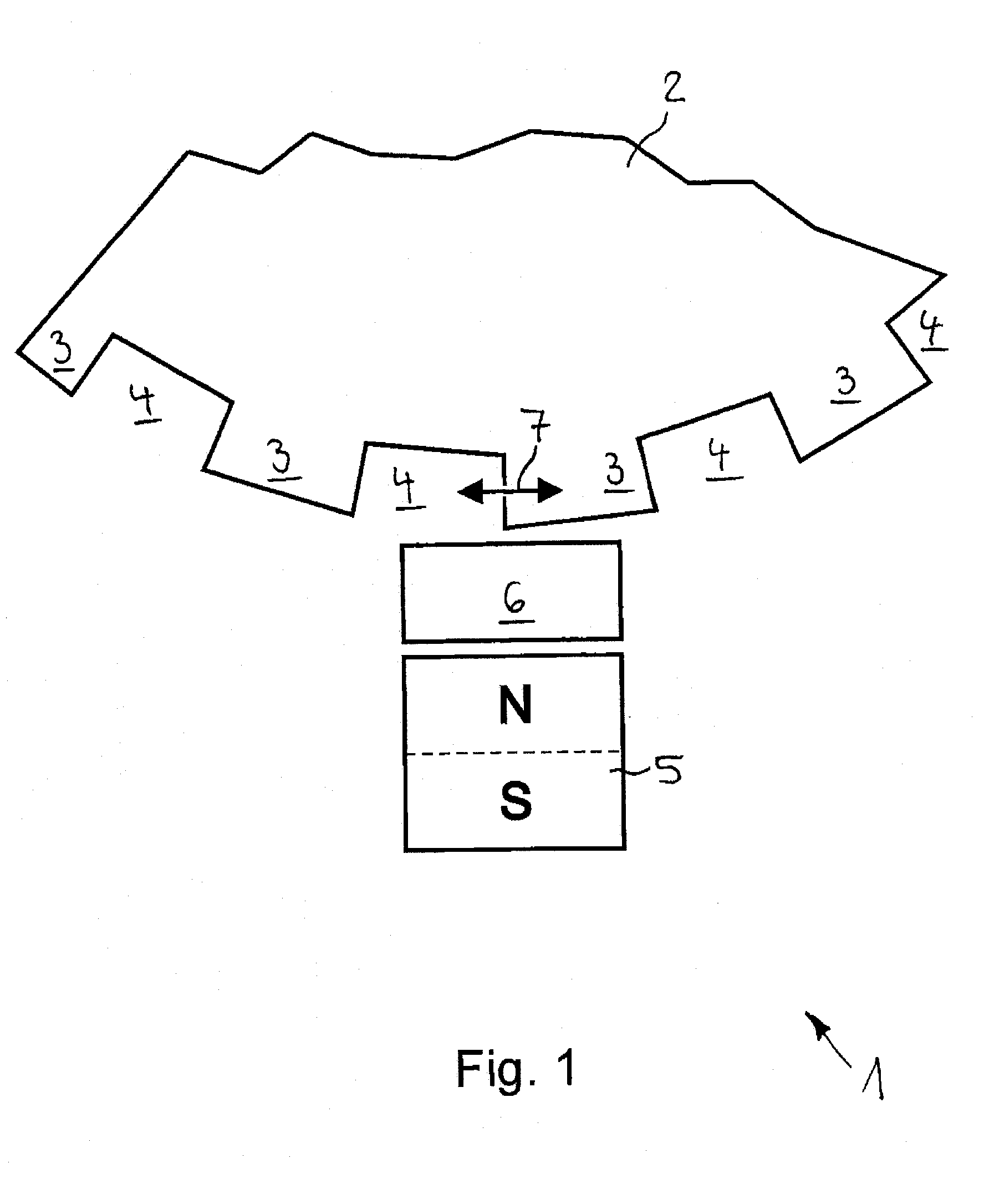
[0026]A measuring device, which is designated as whole with 1 in FIG. 1, for detecting a relative movement has a soft magnetic sensor 2 designed as a gear, which is disposed rotatable around an axis of rotation at a support not shown in greater detail in the drawing. Sensor 2 has at its outer circumference a plurality of teeth 3, which are spaced apart in the circumferential direction and between which tooth spaces 4 are formed.

[0027]Further, a permanent magnet 5 is arranged at the outer circumference of sensor 2 and is separated from sensor 2 by an air gap in the radial direction. Magnet 5 is magnetized approximately radially to the axis of rotation of sensor 2.

[0028]In the air gap, a semiconductor chip 6 is arranged which is oriented with its chip plane parallel to the axis of rotation of sensor 2 and parallel to the direction of motion 7 of teeth 3 and tooth gaps 4 that can be moved past semiconductor chip 6. A magnetic field sensor and a signal processing unit, not shown in grea...


PUM


Abstract

In a method for generating pulse edges, assigned synchronously to the movement of a mechanical part, a magnetic field is generated. At least two measuring signals phase-shifted to one another for the magnetic field are detected. The magnetic field is changed as a function of the movement of the mechanical part in such a way that the measuring signals are modulated. A first measuring signal is compared with at least one first reference value. A second measuring signal is compared with at least one second reference value and / or the value of the first measuring signal is compared with the value of the second measuring signal. When at least one of these comparisons produces an agreement or the result of the relevant comparison changes its sign, a pulse edge is generated.

Description

[0001]This nonprovisional application is a continuation of International Application No. PCT / EP2009 / 008384, which was filed on Nov. 25, 2009, and which claims priority to German Patent Application No. DE 10 2008 059 401.6, which was filed in Germany on Nov. 27, 2008, and which are both herein incorporated by reference.BACKGROUND OF THE INVENTION[0002]1. Field of the Invention[0003]The invention relates to a method for generating pulse edges, assigned synchronously to the movement of a mechanical part, whereby a magnetic field is generated and at least two measuring signals for the magnetic field are detected, whereby the magnetic field is changed as a function of the movement of the mechanical part in such a way that the measuring signals are modulated phase-shifted to one another. In addition, the invention relates to a semiconductor chip into which a magnetic field sensor and a signal processing unit associated therewith are integrated, whereby the magnetic field sensor has at lea...

Claims


Application Information

Patent Timeline
Patent Type & Authority Applications(United States)
IPC IPC(8): G01R33/06G01R33/02
CPCG01D5/145
Inventor FRANKE, JOERGHEBERLE, KLAUS
Owner TDK MICRONAS GMBH
Learn More