A constant current control module, non-isolated step-down circuit and constant current control method

A technology of constant current control and rectification module, applied in energy-saving control technology, electric light source, electrical components, etc., can solve the problems of high cost, large number of peripheral components, and high difficulty in assembling peripheral circuits, so as to reduce system cost and facilitate PCB routing. line, to achieve the effect of LED open circuit protection

Active Publication Date: 2021-04-27
CRM ICBG (WUXI) CO LTD
View PDF5 Cites 0 Cited by
  • Summary
  • Abstract
  • Description
  • Claims
  • Application Information

AI Technical Summary

Problems solved by technology

[0005] In view of at least one shortcoming of the prior art described above, the object of the present invention is to provide a constant current control module, a non-isolated step-down circuit and a constant-current control method, which are used to solve the problem of the peripheral problems of the non-isolated step-down circuit in the prior art. The number of components is large, the cost is high, and the difficulty of peripheral circuit assembly is high

Method used


Image

  • A constant current control module, non-isolated step-down circuit and constant current control method
  • A constant current control module, non-isolated step-down circuit and constant current control method
  • A constant current control module, non-isolated step-down circuit and constant current control method

Examples


Embodiment 1

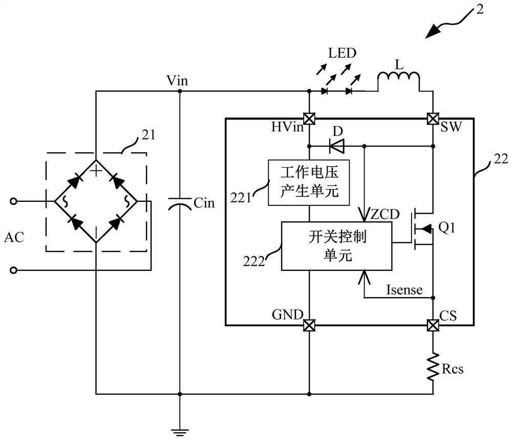
[0056] Such as image 3 As shown, this embodiment provides a non-isolated step-down circuit 2, and the non-isolated step-down circuit 2 at least includes:

[0057] A rectifier module 21 , an input capacitor Cin, a load, an inductor L, a sampling resistor Rcs and a constant current control module 22 .

[0058] Such as image 3 As shown, the rectification module 21 converts the AC signal AC into a DC input voltage Vin.

[0059] Specifically, the rectification module 21 is a rectification bridge, including two parallel diode groups, each diode group includes two diodes connected in series, and the two poles of the AC signal AC are respectively connected between the two diodes of each diode group.

[0060] Such as image 3 As shown, the input capacitor Cin is connected in parallel with the two ends of the rectification module 21 for stabilizing the input voltage Vin.

[0061] Specifically, the upper plate of the input capacitor Cin is connected to the input voltage Vin, and th...

Embodiment 2

[0078] Such as Figure 4 As shown, this embodiment provides a non-isolated step-down circuit 2. The difference between this embodiment and Embodiment 1 is that the drain terminal of the first switching transistor Q1 of this embodiment is connected to the freewheeling diode D A detection resistor R is also connected between the positive electrodes.

[0079] Specifically, such as Figure 4 As shown, the connection node between the detection resistor R and the freewheeling diode D is connected to the switch control unit 222 . The detection resistor R detects the current flowing through the freewheeling diode D, and outputs the detected signal to the switch control unit 222. When the current flowing through the freewheeling diode D is zero, the inductor The current on L just crosses zero, and the switch control unit 222 can directly obtain the demagnetization time Toff of the inductor L accordingly, so as to avoid the influence of the zero-crossing detection time TQR in the quas...

Embodiment 3

[0081] This embodiment provides a non-isolated step-down circuit 2. The difference between this embodiment and Embodiment 1 is that this embodiment uses a second switching tube Q2 to replace the freewheeling diode D in Embodiment 1.

[0082] Specifically, the drain terminal of the second switching transistor Q2 is connected to the output terminal of the rectification module 21, the source terminal is connected to the drain terminal of the first switching transistor Q1, and the gate terminal is connected to the switch control unit 222, through the The switch control unit 222 controls the second switch tube Q2 to realize synchronous rectification and improve the overall efficiency of the system. The connection relationship and principles of other modules and devices of the non-isolated step-down circuit 2 in this embodiment are the same as those in the first embodiment, and will not be repeated here.


PUM


Abstract

The present invention provides a constant current control module, a non-isolated step-down circuit and a constant current control method, comprising: a rectification module; a load; an inductor; a sampling resistor providing a current sampling signal; and a zero-crossing detection signal and a current sampling signal according to the inductor A constant current control module for constant current control of the load. In the initial stage, the first switching tube is in the conduction state, and the inductor is in the energy storage state. As the input voltage increases, the current sampling signal increases continuously. When the current sampling signal reaches a preset value, the first switching tube is turned off, and the first The conduction time of the switch tube is determined; the inductor starts to discharge, the demagnetization time of the inductor and the zero-crossing detection time of the quasi-resonant mode are determined through the quasi-resonant mode, and a working cycle is completed, and the output current is constant in each working cycle. The invention has few peripheral components, low system cost, high output current precision and high system efficiency; at the same time, the LED open circuit protection is realized by using the current sampling signal or the inductance demagnetization time, and has comprehensive functions.

Description

technical field [0001] The invention relates to the field of integrated circuit design, in particular to a constant current control module, a non-isolated step-down circuit and a constant current control method. Background technique [0002] The non-isolated step-down circuit replaces the RC step-down circuit and has become the most commonly used structure of the step-down circuit. Normally, in order to reduce costs, non-isolated step-down circuits use three-terminal devices for constant current step-down applications. Such as figure 1 As shown, a non-isolated step-down circuit in the prior art includes a fuse F1, a rectifier module 11, an input capacitor Cin, a diode D, an inductor L, an output capacitor Cout, an LED light string, a first resistor R1, and a second resistor R2 . A constant current control chip 12 and a power supply filter capacitor Cvdd; the constant current control chip 12 includes a power switch tube Q (three-terminal device) and a constant current contr...

Claims


Application Information

Patent Timeline
Patent Type & Authority Patents(China)
IPC IPC(8): H05B45/30H05B45/37H05B45/345H05B45/50H05B44/00
CPCY02B20/30Y02B20/40
Inventor 刘军胡津华吴泉清
Owner CRM ICBG (WUXI) CO LTD
Why Eureka
Try Eureka