
Eureka
For R&D, Eureka makes reading and utilizing patents & technical documents easy.
Eureka AIR
Designed for self-driven R&D workflows. Generate viable solutions, solve complex R&D challenges, empower your innovation with AI.

Eureka Materials
Designed for material experts only. Revolutionize your material R&D, from search, analyze, to developing new materials.

TechResearch
Generate reliable direction feasibility study reports for your R&D in just a few steps.

TechSeek
Discover and master advanced knowledge NOW. Basics, ideas, possibilities, all at once.

TechMind
As an expert in R&D Theories, TechMind can generates customized viable solutions instantly.

TechRisk
Analyze your overall solution with one click, know your potential R&D risks in advance.

TechMonitor
Get weekly tech updates, stay abreast of the latest tech innovations and key insights.
Airflow control apparatus
- Summary
- Abstract
- Description
- Claims
- Application Information
AI Technical Summary
Benefits of technology
Problems solved by technology
Method used
Image

Examples
first embodiment
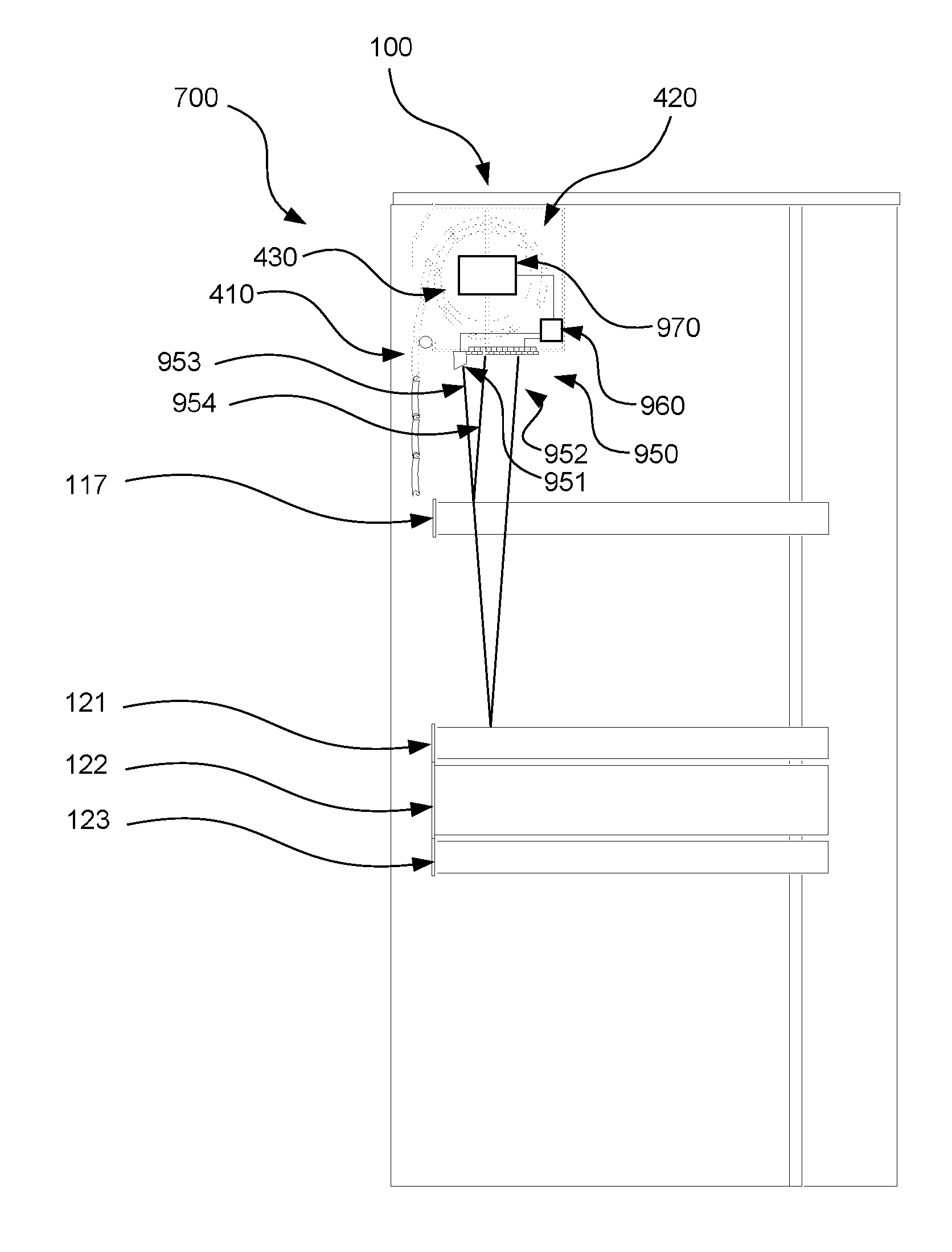
[0022]FIG. 4 shows a first embodiment in a first configuration, with a fully filled rack. As shown, there is accordingly provided an airflow control device 400 for an electronic hardware rack 100 adapted to house a plurality of electronic hardware modules 111 to 123 of a specified width. The airflow control device 400 comprises a flexible web 410 of at least the specified width and a magazine 420 adapted to receive the part of the flexible web 410 that is not deployed. As shown in FIG. 4 the whole flexible web 410 is stored in the magazine 420.
[0023]The specified width is conventionally 480 mm (19 inches) or 580 mm (23 inches), although many other widths are possible.
[0024]The height of each the hardware modules is conventionally a respective integer multiple of a standard unit height, and the rack 100 is dimensioned so as to house hardware whose total height is a further integer multiple of the standard unit height, and wherein the airflow control device 400 is adapted to deploy th...
second embodiment
[0031]FIG. 8 shows a As shown in FIG. 8, rather than the web 410 being wound onto a drum mounted within the magazine, the magazine 800 comprises a planar tray disposed at right angles to the plane in which the web 410 is deployed, i.e., in a conventional rack configuration, in a horizontal plane. The magazine comprises a rack mountable case one standard unit in height, with the retracted web 410 lying flat within it. There is further provided an outlet roller 841 to assist a smooth deployment of the web 410 as required. As shown there is further provided a tensioning system 844, which may for example comprise a spring or elastic member, which is coupled to the extremity of the web 410 by a cable 842. In order to efficiently use the available volume, the tensioning system 844 is disposed below the space reserved for the retracted web 410, with the cable 842 passing around a roller 743 to the reverse the direction of tension provided. Additionally or alternatively there may be provid...
PUM
 Abstract
Description
Claims
Application Information
 - R&D Engineer
- R&D Manager
- IP Professional
- Industry Leading Data Capabilities
- Powerful AI technology
- Patent DNA Extraction
Browse by: Latest US Patents, China's latest patents, Technical Efficacy Thesaurus, Application Domain, Technology Topic, Popular Technical Reports.
© 2024 PatSnap. All rights reserved.Legal|Privacy policy|Modern Slavery Act Transparency Statement|Sitemap|About US| Contact US: help@patsnap.com