Working method for sapphire substrate

a sapphire substrate and working method technology, applied in the direction of fine working devices, manufacturing tools, electric devices, etc., can solve the problems of poor productivity, achieve the effect of improving productivity, reducing the amount of cutting blade abrasion, and improving productivity

Inactive Publication Date: 2011-12-01
DISCO CORP
View PDF5 Cites 23 Cited by
  • Summary
  • Abstract
  • Description
  • Claims
  • Application Information

AI Technical Summary

Benefits of technology

[0008]Therefore, it is an object of the present invention to provide a working method for a sapphire substrate which can divide a sapphire substrate along a set planned dividing line while the abrasion amount of a cutting blade is reduced.
[0011]In the working method for a sapphire substrate according to the present invention, the cutting groove forming step of a cutting groove, which serves as a start point of break, along a planned division line on a sapphire substrate is set such that the rotational speed of the cutting blade is 20000 to 35000 rpm, the cutting-in depth of the cutting blade is 5 to 15 μm and the working feeding speed is 50 to 150 mm / second. Therefore, the cutting edge which configures the cutting blade is not damaged, and the abrasion amount of the cutting blade decreases and the productivity can be improved without causing any break with the sapphire substrate. Particularly, in the working method for a sapphire substrate according to the present invention, since the working feeding speed is set to 50 to 150 mm / second, working can be carried out at a working speed as high as 15 to 50 times the working feeding speed (3 mm / second) which has conventionally been regarded as a common sense in cutting working of a sapphire substrate, and the productivity can be improved. Further, the abrasion amount of the cutting blade decreases to equal to or less than ½, and the exchanging frequency of the cutting blade can be reduced to equal to or less than ½.

Problems solved by technology

However, there is a problem that the cutting blade is abraded severely and must be exchanged frequently, which is uneconomical and is poor in productivity.

Method used


Image

  • Working method for sapphire substrate
  • Working method for sapphire substrate
  • Working method for sapphire substrate

Examples


experiment example

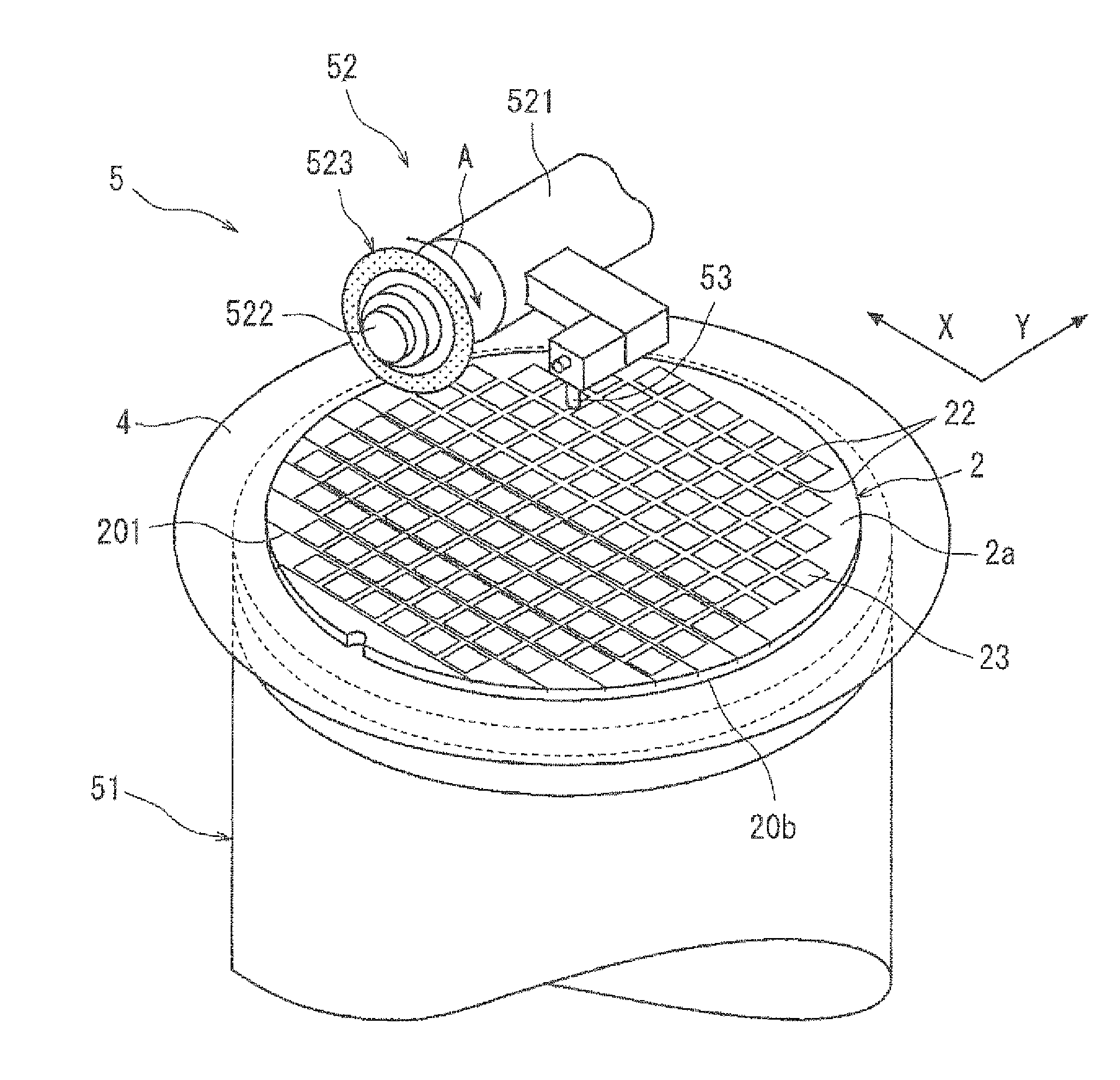
[0031]A sapphire substrate was cut using a cutting blade including a cutting edge formed from an electroformed blade formed by securing diamond grain of a particle size of 3 to 4 μm by nickel plating and having a thickness of 30 μm and an outer diameter of 52 mm. The working conditions at this time were that the cutting-in depth was 15 μm; the rotational speed of the cutting blade was 30000 rpm; the working feeding speed was set stepwise within the range of 1 to 150 mm / second; and the cutting working was carried out for 1 m. The following results were obtained by the experiment.

[0032](1) In the case where the working feeding speed was 1 mm / second, the abrasion amount of the cutting edge which configured the cutting blade was 7 μm / working length 1 m.

[0033](2) In the case where the working feeding speed was 3 mm / second, the abrasion amount of the cutting edge which configured the cutting blade was 6 μm / working length 1 m.

[0034](3) In the case where the working feeding speed was 10 mm / ...


PUM

PropertyMeasurementUnit
rotational speedaaaaaaaaaa
thicknessaaaaaaaaaa
particle sizeaaaaaaaaaa

Abstract

A working method for a sapphire substrate for dividing a sapphire substrate along a set planned dividing line includes a cutting groove forming step of positioning a cutting blade, which includes a cutting edge to which diamond grain is secured by nickel plating, to a planned dividing line of the sapphire substrate and feeding the cutting blade and the sapphire substrate relative to each other for working while rotating the cutting blade to form a cutting groove, which serves as a start point of break, along the planned division line on the sapphire substrate, and a breaking step of applying external force to the sapphire substrate, for which the cutting groove forming step is carried out, to break the sapphire substrate along the planned dividing line along which the cutting groove is formed. The cutting groove forming step is set such that a rotational speed of the cutting blade is 20000 to 35000 rpm, a cutting-in depth of the cutting blade is 5 to 15 μm and a working feeding speed is 50 to 150 mm / second.

Description

BACKGROUND OF THE INVENTION[0001]1. Field of the Invention[0002]This invention relates to a working method for a sapphire substrate for dividing a sapphire substrate, which is used as a substrate of an optical device wafer or the like, along a planned dividing line set in advance.[0003]2. Description of the Related Art[0004]In an optical device manufacturing process, an optical device layer made of a gallium nitride-based compound semiconductor is layered on the surface of a sapphire substrate of a substantially disk shape, and a plurality of optical devices such as light emitting diodes or laser diodes are formed in different regions partitioned by a plurality of planned dividing lines formed in a lattice pattern. Then, the optical device wafer is divided along the planned dividing lines to manufacture the individual optical devices.[0005]As a dividing method for dividing an optical device wafer along planned dividing lines described above, a method has been proposed wherein a puls...

Claims


Application Information

Patent Timeline
Patent Type & Authority Applications(United States)
IPC IPC(8): H01L21/78
CPCB28D5/0029B28D5/0011
Inventor OKAMURA, TAKASHI
Owner DISCO CORP
Why Eureka
Try Eureka