
Endoscope apparatus

a technology of endoscope and endoscope, which is applied in the field of endoscope apparatus, can solve the problems of increasing production cost, and achieve the effects of reducing the flow rate of the delivery, and suppressing the temperature rise of the heat-producing devi

Inactive Publication Date: 2011-12-01
OLYMPUS CORP
View PDF21 Cites 45 Cited by
  • Summary
  • Abstract
  • Description
  • Claims
  • Application Information

AI Technical Summary

Benefits of technology

[0008]The present invention has been made in view of the foregoing circumstances, and an object of the present invention is to provide an endoscope apparatus which is devised to be capable of minimizing the increase in production cost though having a distal-end cooling system.
[0012]In the endoscope apparatus according to the present invention, it is desirable that the endoscope apparatus performs one of the following two operations when the cleaning liquid is discharged: temporarily stopping delivery of the coolant; and decreasing a flow rate of the delivery of the coolant.
[0013]In the endoscope apparatus according to the present invention, it is desirable that the endoscope apparatus temporarily suppress temperature rise of the heat-producing device when the cleaning liquid is discharged.
[0014]In the endoscope apparatus according to the present invention, it is desirable that the endoscope apparatus temporarily suppress the temperature rise of the heat-producing device by a reduction in power supplied to the heat-producing device.

Problems solved by technology

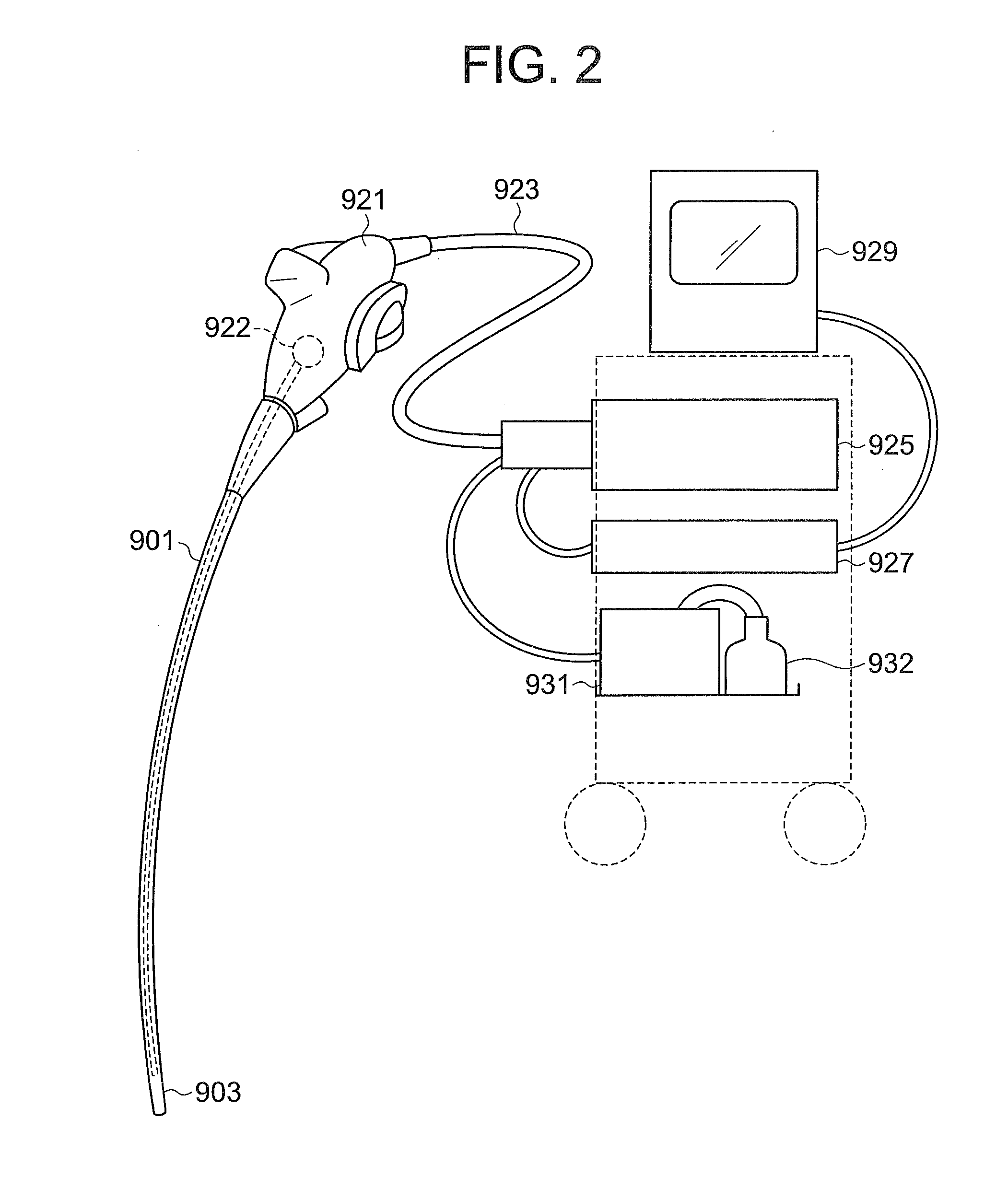
However, in the above-described conventional endoscope apparatus, the pump 922 is newly incorporated into the handling section 921 of the endoscope, which has been a cause of an increase in production cost, when compared with an endoscope apparatus having no cooling system at the distal end.

Method used


Image

  • Endoscope apparatus
  • Endoscope apparatus
  • Endoscope apparatus

Examples


first embodiment

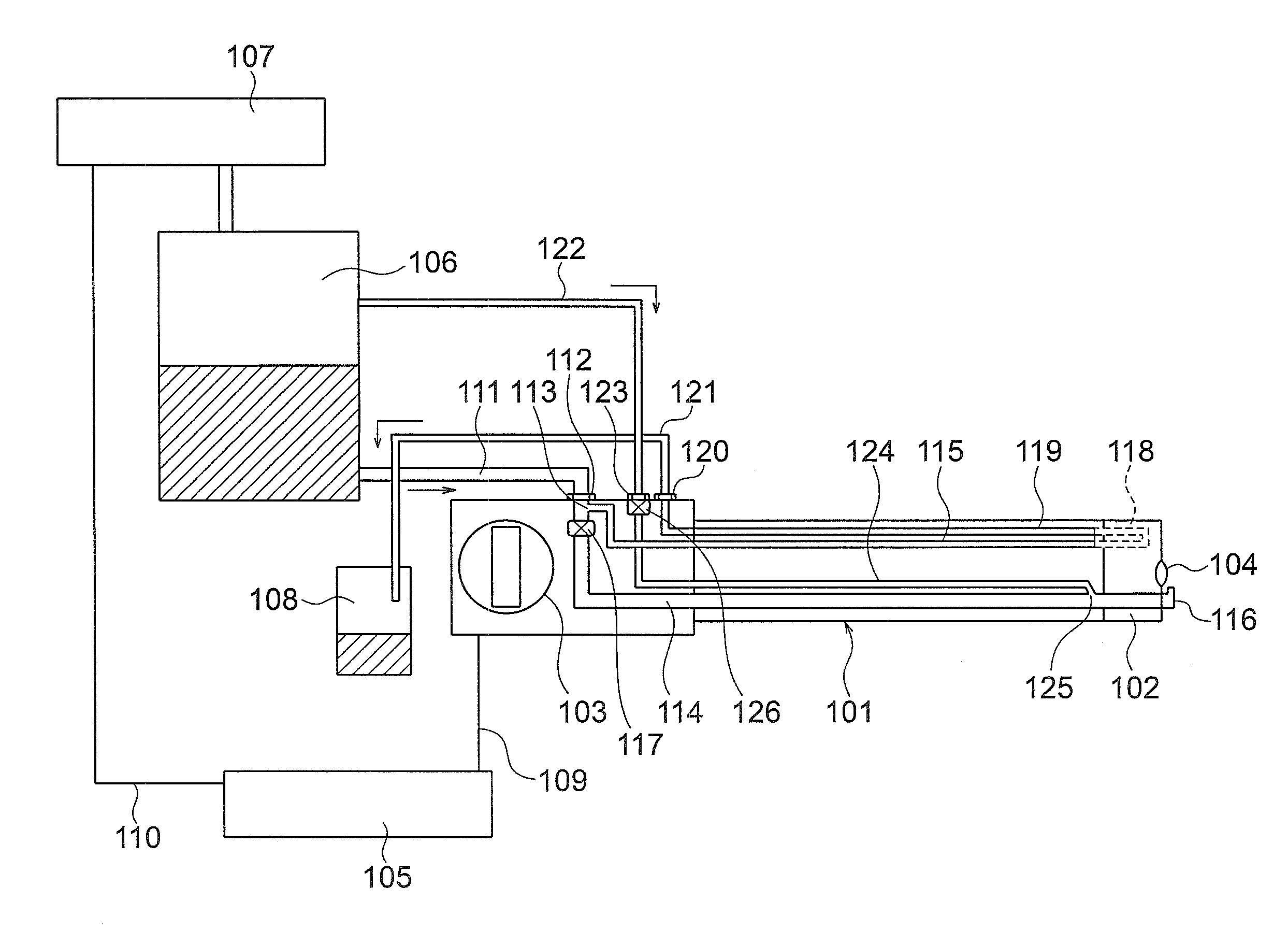
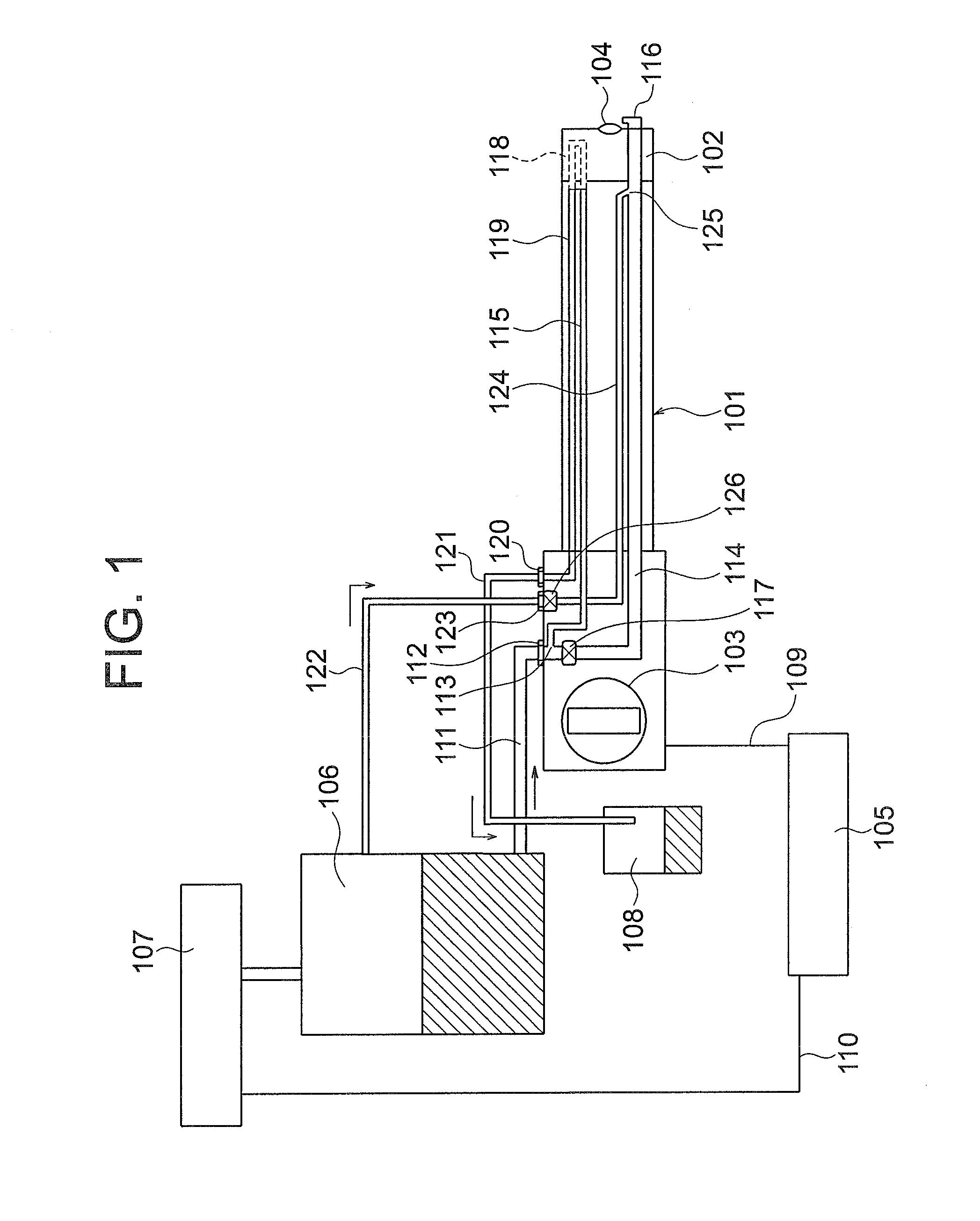
[0019]A first embodiment of the endoscope apparatus will be hereinafter discussed with reference to FIG. 1. FIG. 1 schematically shows the structure of the first embodiment of the endoscope apparatus.

[0020]An endoscope 101 of the endoscope apparatus is provided, at a distal end side and a proximal end side, with a distal end portion 102 and a handling section 103, respectively. The endoscope 101 is provided inside the distal end portion 102 with an object lens 104 and heat-producing electronic components (heat-producing devices) not shown in the drawings such as an image pickup unit and an illumination LED (light-emitting diode). The endoscope apparatus is provided outside the endoscope 101 with a controller 105, a water tank 106, a compressor 107 (liquid sending system, pressurizing system) and a drain tank 108. The water tank 106 contains a cleaning liquid and a coolant, the compressor 107 operates to send the cleaning liquid and the coolant to the endoscope 101 by applying pressu...

second embodiment

[0042]A second embodiment of the endoscope apparatus is identical in structure to the first embodiment of the endoscope apparatus except that the flow rate of a cleaning liquid is ensured with no reduction in the flow rate of a coolant by temporarily increasing the pressure of the compressor 107 when the valve 117 moves to the open state.

The controller of the second embodiment of the endoscope apparatus controls the operation of the compressor 107 in a manner to increase the pressure to the water tank 106 upon detecting that the valve 117 moves to the open state. This control makes it possible to supply the same quantity of coolant as in the closed state of the valve 117 to the flow channel 118 through the coolant sending tube 115 even when the valve 117 moves to the open state.

[0043]In this endoscope apparatus, the compressor needs an extra capacity, devices of the endoscope apparatus that are installed outside the endoscope increase in size, and an improvement in resistance to pre...


PUM


Abstract

Provided is an endoscope apparatus which is equipped with an endoscope including an object lens, a distal end portion and a handling section, a heat-producing device being incorporated into the distal end portion. The endoscope apparatus includes: a cleaning system which transiently discharges a cleaning liquid toward the object lens to clean the object lens; a cooling system which refluxes a coolant in the distal end portion to cool the heat-producing device; a liquid sending system, installed outside the endoscope, for supplying the cleaning liquid and the coolant; and a liquid-sending pressurizing system shared between the cleaning liquid and the coolant.

Description

CROSS-REFERENCE TO RELATED APPLICATION[0001]The present application is based upon and claims the benefit of priority from the prior Japanese Patent Application No. 2010-120493 filed on May 26, 2010; the entire contents of which are incorporated herein by reference.BACKGROUND OF THE INVENTION[0002]1. Field of the Invention[0003]The present invention relates to an endoscope apparatus.[0004]2. Description of the Related Art[0005]In association with sophistication in the capabilities of endoscope apparatuses, the quantity of heat produced at the distal end of an endoscope is on the increase. Accordingly, a technique of refluxing fluid in the distal end to provide cooling for the same has been desired. An endoscope apparatus equipped with such a distal-end cooling system is disclosed in, e.g., Japanese Published Patent Application Publication No. 2007-7322.[0006]The endoscope apparatus disclosed in Japanese Published Patent Application Publication No. 2007-7322 will be hereinafter discus...

Claims


Application Information

Patent Timeline
IPC IPC(8): A61B1/12
CPCA61B1/126A61B1/015
Inventor YASUNAGA, SHINJI
Owner OLYMPUS CORP
Learn More