Tabbed compression plate and method of use

a compression plate and tab technology, applied in the field of orthopaedic implants, can solve the problems of fragments or devices that are difficult to shorten, lose interfragmental compression, and orthopedic implants that are not very effective in maintaining interfragmental, and achieve the effect of facilitating direct compression

Inactive Publication Date: 2011-12-01
EXTREMITY MEDICAL
View PDF1 Cites 54 Cited by
  • Summary
  • Abstract
  • Description
  • Claims
  • Application Information

AI Technical Summary

Benefits of technology

[0008]Another object of the invention is to provide a novel and useful orthopedic fixation assembly that may be utilized to secure multiple bones fragments or bones together.
[0009]Another object of the invention is to provide an orthopedic fixation assembly that may be utilized to secure the implant bone interface

Problems solved by technology

These orthopedic implants apply initial interfragmental compression, however, due to the biological conditions of bone resorbtion (i.e., removal of bone), which may be sometimes caused from micromotion across lines of fracture, interfragmental compression is lost as implants loosen due to the resorbtion of fragmental contacting surfaces, thereby causing the fragments or device to shorten.
Thus, these orthopedic implant devices are not very effective in maintaini

Method used


Image

  • Tabbed compression plate and method of use
  • Tabbed compression plate and method of use
  • Tabbed compression plate and method of use

Examples


Embodiment Construction

[0028]The invention may be understood more readily by reference to the following detailed description of preferred embodiment of the invention. However, techniques, systems, and operating structures in accordance with the invention may be embodied in a wide variety of forms and modes, some of which may be quite different from those in the disclosed embodiment. Consequently, the specific structural and functional details disclosed herein are merely representative, yet in that regard, they are deemed to afford the best embodiment for purposes of disclosure and to provide a basis for the claims herein, which define the scope of the invention. It must be noted that, as used in the specification and the appended claims, the singular forms “a”, “an”, and “the” include plural referents unless the context clearly indicates otherwise.

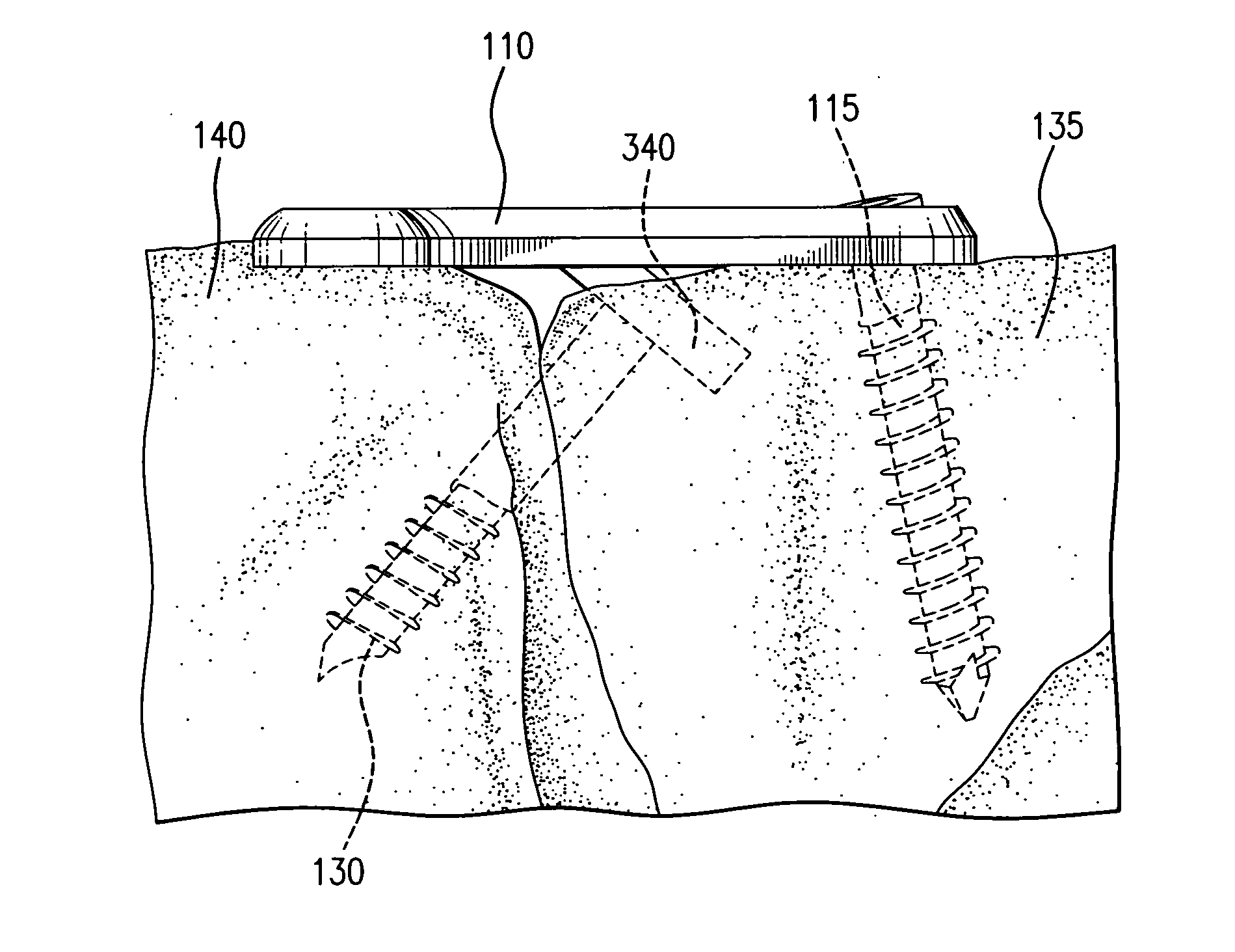
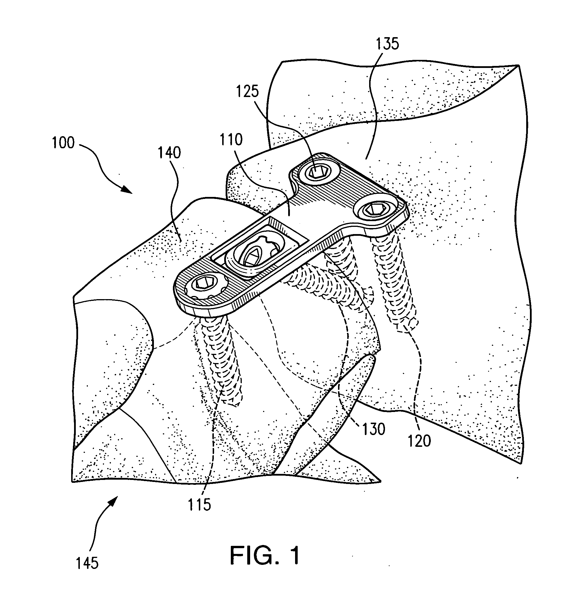
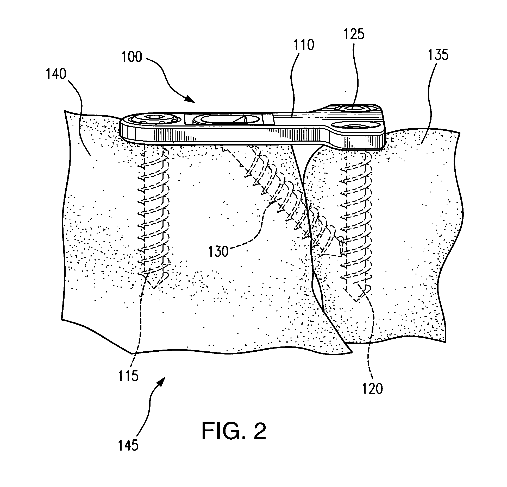
[0029]Referring now to FIGS. 1-2, there is shown an orthopedic fixation assembly 100 which is made in accordance with the teachings of the preferred embodiment ...


PUM


Abstract

An orthopedic fixation system includes a compression plate member, a lag screw member, and a plurality of threaded screw members for applying compression across a fracture site. The compression plate member has a generally planar body, an upper surface, and bone contacting surface. The planar body includes a plurality of through-apertures and a hinged tab member having an elongated through aperture, which is adapted to receive the lag screw member and cause the tab member to recess towards a bone divot formed in the underlying bone. The compression plate member is also adapted to receive the plurality of screw members within the through-apertures for fixably and threadably coupling the compression plate member across a fracture site. The lag screw member applies a direct compressive force across the fracture site through the deformable tab that is recessed in the bone divot.

Description

CROSS-REFERENCE TO RELATED APPLICATIONS[0001]This non-provisional application claims the benefit of provisional application No. 61 / 340,613, filed Mar. 19, 2010, which is herein incorporated by reference in its entirety.FIELD OF THE INVENTION[0002]This invention relates to the field of orthopedic implant devices and, particularly, to an orthopedic compression plate and screw assembly for providing a direct compressive force across a fracture site to secure two or more bone fragments or bones together.BACKGROUND OF THE INVENTION[0003]Orthopedic implant devices are often used to repair or reconstruct bones and joints caused by bone fractures, degenerative bone conditions, or other similar types of injuries. Frequently, these orthopedic devices require that bone fragments, due to bone fractures or bones cut by a surgical operation (i.e., an osteotomy), must be kept together for long periods of time or short periods intraoperatively under a sustained force across the fractures site in or...

Claims


Application Information

Patent Timeline
IPC IPC(8): A61B17/80
CPCA61B17/8061A61B17/8014
Inventor DONLEY, BRIANARELLANO, LUISGANNOE, JAMYTYBER, JEFF
Owner EXTREMITY MEDICAL
Why Eureka
Try Eureka