Projector mount and method and system for installing a device in a suspending ceiling

a projector and ceiling technology, applied in the field of mounting, can solve the problems of time-consuming and difficult installation, heavy or bulky devices, and heavy and bulky devices, and achieve the effect of simple and more effective method and system

Inactive Publication Date: 2011-12-08
LEGRAND AV INC
View PDF3 Cites 1 Cited by
  • Summary
  • Abstract
  • Description
  • Claims
  • Application Information

AI Technical Summary

Benefits of technology

[0007]The present invention meets the needs of the industry for a simpler and more effective method and system for mounting a projector or other ceiling mounted device above a suspended ceiling such that the mount or device can be installed in a minimal amount of time by one person.

Problems solved by technology

A drawback of mount devices such as the SL-236SP is that they can tend to be heavy and bulky, requiring at least two persons for installation in the room.
Also, the installation can be time-consuming and difficult.
Such devices can likewise be heavy or bulky, such that installation by one person can be difficult or impossible.

Method used


Image

  • Projector mount and method and system for installing a device in a suspending ceiling
  • Projector mount and method and system for installing a device in a suspending ceiling
  • Projector mount and method and system for installing a device in a suspending ceiling

Examples


Embodiment Construction

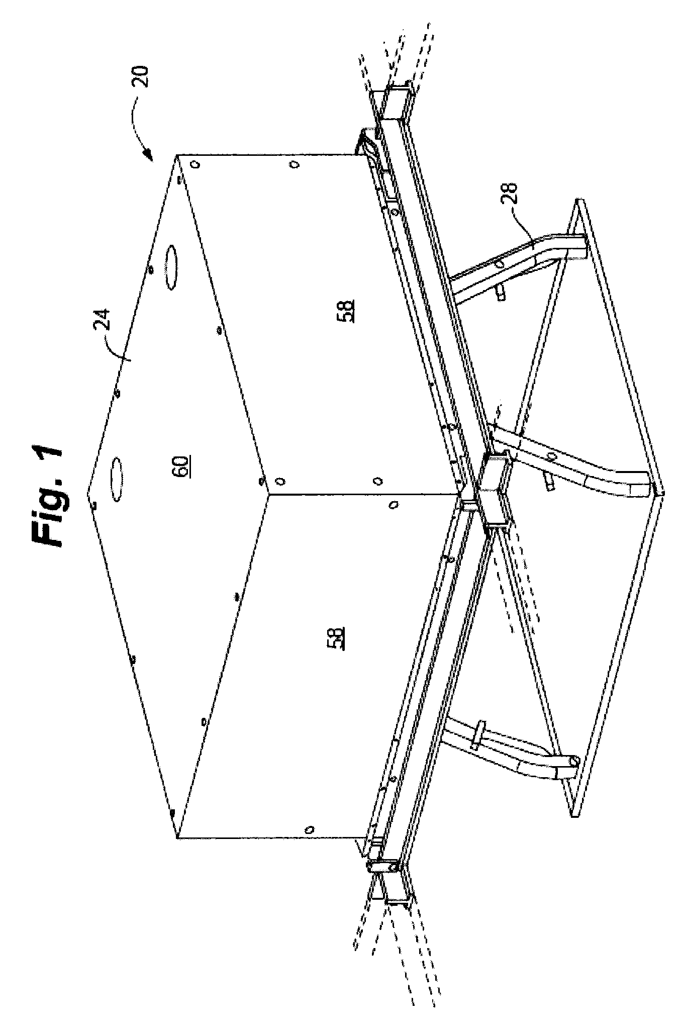
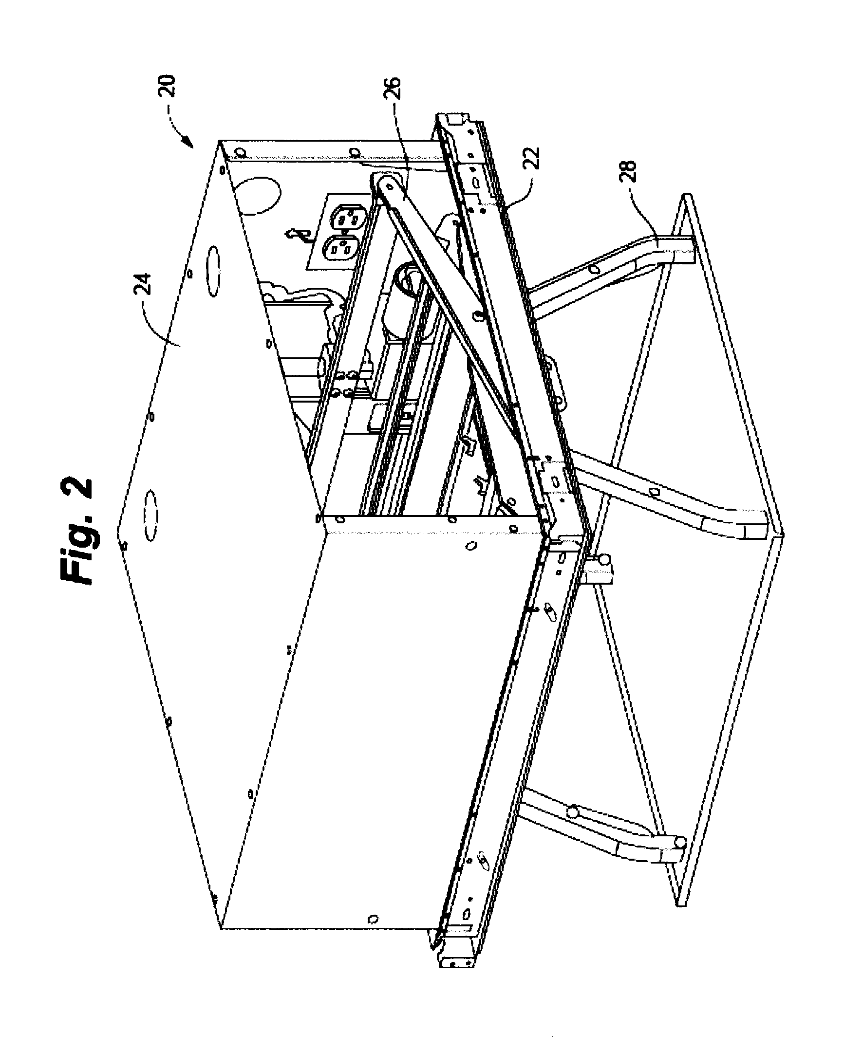
[0036]A projector mount 20 according to embodiments of the invention is depicted in FIGS. 1-12. Mount 20 generally includes ceiling grid interface frame 22, mount housing 24, lift assembly 26, and cradle 28. As depicted in FIG. 3, frame 22 generally includes rails 30, 32, 34, 36, grid member interfaces 38, and optionally electrical receptacle attachment 40. Each of rails 30, 32, 34, 36, includes a vertical web portion 42 and outwardly extending flange portions 44, 46. Vertical slots 48 are defined in each rail proximate corners 50, 52, 54, 56, of frame 22. Grid member interfaces 38 are attached to the outside faces of web portions 42 of rails 32, 36, at each end of the rail.

[0037]Mount housing 24 generally includes a plurality of side panels 58, and a top panel 60. Each spring latch assembly 62 generally includes L-shaped latch body 66 and biasing spring 68. As depicted in FIGS. 6 and 13, spring latch assemblies 62 are pivotally coupled to the inside face of sides 58 at pivots 64, w...


PUM

PropertyMeasurementUnit
timeaaaaaaaaaa
weightaaaaaaaaaa
structureaaaaaaaaaa

Abstract

A system for installing a device in a suspended ceiling grid includes a device housing, and a frame adapted to be received in the suspended ceiling grid. The device housing is received in an aperture defined by the frame. A plurality of structures releasably secures the device housing to the frame. Embodiments of the invention provide simpler and more effective methods and systems for mounting ceiling mounted devices above a suspended ceiling such that the device can be installed in a minimal amount of time by one person.

Description

RELATED APPLICATIONS[0001]This application claims the benefit of U.S. Provisional Patent Application Ser. No. 61 / 351,523, entitled PROJECTOR MOUNT AND METHOD AND SYSTEM FOR INSTALLING A PROJECTOR MOUNT IN A SUSPENDED CEILING, filed on Jun. 4, 2010, said application hereby fully incorporated herein by reference.FIELD OF THE INVENTION[0002]The present invention relates to mounts, and more specifically, to methods and systems for mounting devices in a suspended ceiling.BACKGROUND OF THE INVENTION[0003]The use of visual media in business settings has proliferated greatly in recent years due to the widespread availability and decreasing cost of visual projection systems. It is now common in commercial settings to have a projector, screen, or other visual media device more or less permanently installed in one or more conference or meeting rooms.[0004]In some meeting room settings, it is desirable to have a projector, screen, or other media device that is always available for use, but that...

Claims


Application Information

Patent Timeline
Patent Type & Authority Applications(United States)
IPC IPC(8): F16M13/02B23P11/00
CPCF16M11/046Y10T29/49947F16M13/02F16M11/18
Inventor DITTMER, JAYWARREN, MIKE
Owner LEGRAND AV INC
Why Eureka
Try Eureka