
Positive displacement power extraction compensation device

a power extraction and compensation device technology, applied in the direction of engine starters, machines/engines, turbine/propulsion engine ignition, etc., can solve the problems of preventing the operation of an engine, causing significant difficulty in starting the engine, and design not working,

Inactive Publication Date: 2011-12-08
LAWSON JR T TOWLES
View PDF10 Cites 36 Cited by
  • Summary
  • Abstract
  • Description
  • Claims
  • Application Information

AI Technical Summary

Benefits of technology

[0028]The present invention is used during certain operating regimes and for starting an open cycle engine. The invention compensates for physical differences between positive displacement devices and the compressors and turbines found in gas turbine engines. These physical differences prevent operation of an engine which is similar to a gas turbine but uses positive displacement devices in place of both the compressor section and the turbine section.
[0029]An object of the present invention is to integrate a positive displacement device in the role of primary power extraction device in an engine where the role of compressor is assumed by a similar positive displacement device. This integration is mainly related to the relative size and speeds of the two devices. The integration also requires other mechanisms particular to this system for starting and enhanced transient response.
[0032]It is therefore the object of the present invention to arrange the PDC and the PED relative to each other, and to provide a mechanism for overcoming the difficulties of starting and operating a device according to this design.

Problems solved by technology

These physical differences prevent operation of an engine which is similar to a gas turbine but uses positive displacement devices in place of both the compressor section and the turbine section.
The important point is that if the engine were built so that it moves equal volumes of air at a given RPM, the combustion gases exert as much force on the PDC shaft as on the PED shaft, assuming the same efficiency, and such a design would not work.
A design where the PED is of an effective greater displacement, whether because it displaces more per revolution or because it is geared to run faster than the PDC, poses a significant difficulty when starting the engine.

Method used


Image

  • Positive displacement power extraction compensation device
  • Positive displacement power extraction compensation device
  • Positive displacement power extraction compensation device

Examples


Embodiment Construction

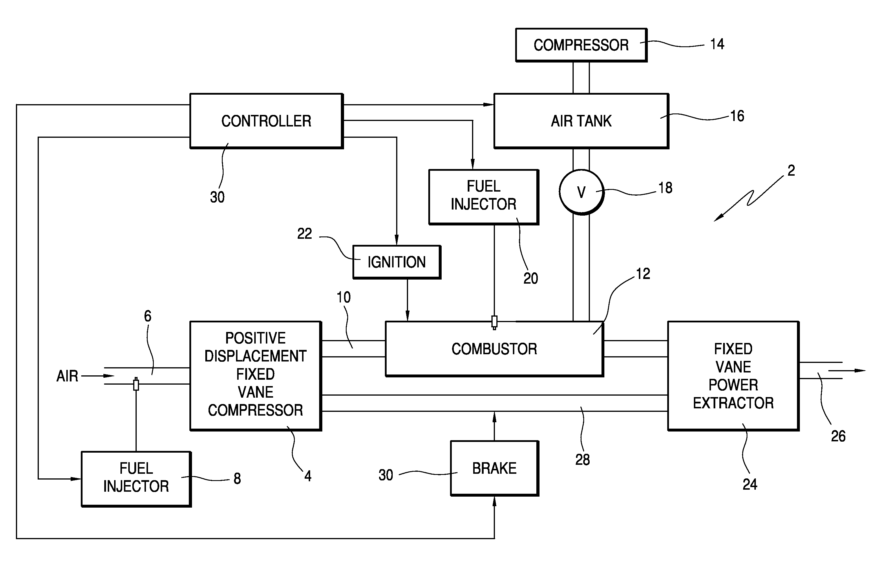
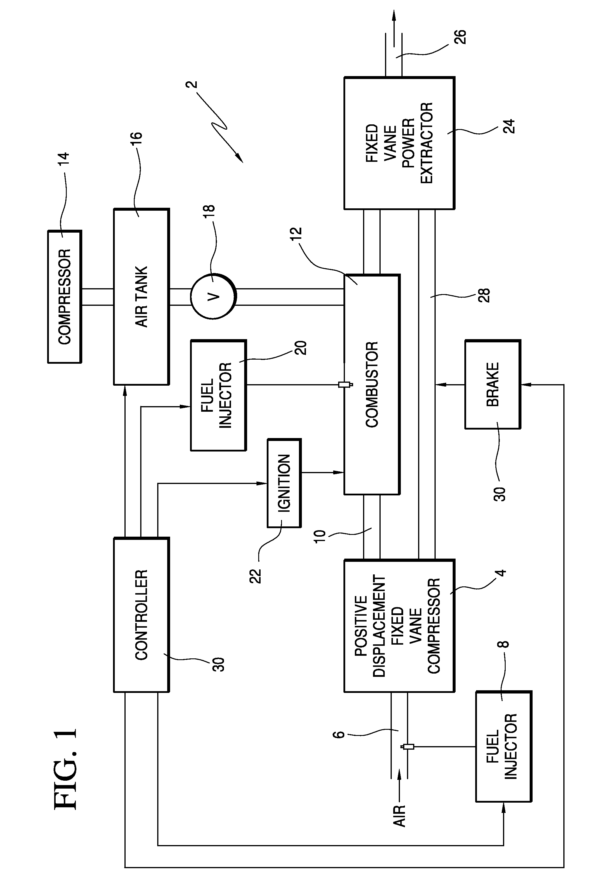
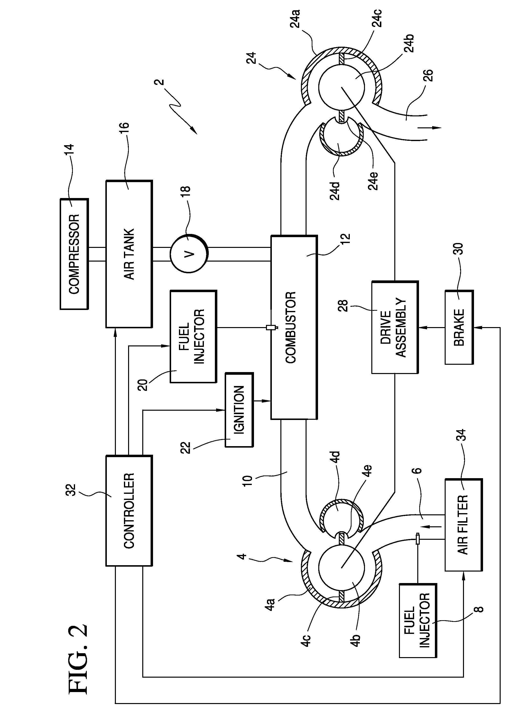
[0037]Referring first to FIG. 1, there is shown an engine 2 which includes a compressor in the form of a positive displacement fixed vane compressor 4. The positive displacement fixed vane compressor compresses air supplied to an inlet 6 of the compressor. A fuel injector 8 is also connected with the air inlet for injecting fuel into the air supply. A fluid conduit 10 connected with the compressor 4 delivers output fluid to a combustor 12. The combustor 12 further receives air for combustion of the fluid. More particularly, a compressor 14 provides pressurized air which is stored in a tank 16. A valve 18 meters the volume of air delivered from the tank to the combustor during starting of the engine, during periods of transient engine power, or during other periods where a low pressure in the combustor could adversely affect combustion. A fuel injector 20 injects fuel into the combustor and an ignition device 22 is connected with the combustor to initiate combustion of the air and fu...


PUM


Abstract

A positive displacement power extraction compensation device is used to start and control the operation of engines. The device includes a positive displacement fixed vane compressor having a rotor connected with a drive shaft, a combustor connected with the compressor and a positive displacement power extraction device also having a rotor connected with a drive shaft. The compressor and power extraction devices are configured to displace unequal volumes of air at a given speed, so that combustion gases from the combustor exert less force on the compressor drive shaft as on the power extraction device drive shaft.

Description

[0001]This application claims the benefit of U.S. provisional application No. 60 / 184,119 filed Jun. 4, 2009.FIELD OF THE INVENTION[0002]The present invention relates to the substitution of positive displacement devices of a certain type for traditional compressors and turbines in gas turbines.BACKGROUND OF THE INVENTION[0003]Gas turbines have three basic parts. In its simplest form, the three components are the compressor, the combustor and the turbine. Energy extracted from the turbine is used to drive the compressor, which compresses air so that it may be mixed with fuel and burned in the combustor. The burnt fuel then exits the combustor through the turbine which rotates in response. The turbine drives the compressor and ancillary components. The range of gas turbines from turbojets to turbo shafts is defined by how much energy is extracted as shaft power.[0004]Turbojets extract as little energy as possible and still run various components. The primary design goal of a turbojet i...

Claims


Application Information

Patent Timeline
IPC IPC(8): F02C7/26F02C6/04
CPCF02C3/055F02C7/26F02C6/04
Inventor LAWSON, JR., T. TOWLES
Owner LAWSON JR T TOWLES
Learn More