Underwater Vehicle Bouyancy System

a technology for underwater vehicles and bouyancy systems, which is applied to waterborne vessels, underwater equipment, special-purpose vessels, etc., can solve the problems of limited energy-efficient operation of existing underwater vehicles, and achieve the effect of optimizing the pumping ra

Inactive Publication Date: 2011-12-08
IROBOT CORP
View PDF4 Cites 7 Cited by
  • Summary
  • Abstract
  • Description
  • Claims
  • Application Information

AI Technical Summary

Benefits of technology

[0010]The present teachings further provide a multiple stage variable buoyancy device for an autonomous underwater vehicle that includes a pump and motor combination with a continuous variable transmission that can electronically adapt to a torque-speed curve to rapidly obtain an optimal pumping rate for changing buoyancy.

Problems solved by technology

The energy-efficient operation of existing underwater vehicles is therefore limited to a particular band of underwater depths.

Method used


Image

  • Underwater Vehicle Bouyancy System
  • Underwater Vehicle Bouyancy System
  • Underwater Vehicle Bouyancy System

Examples


Embodiment Construction

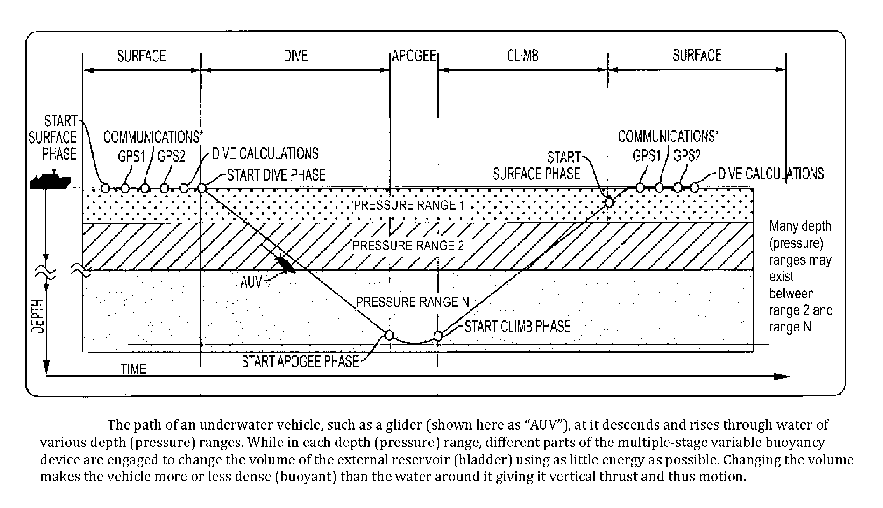
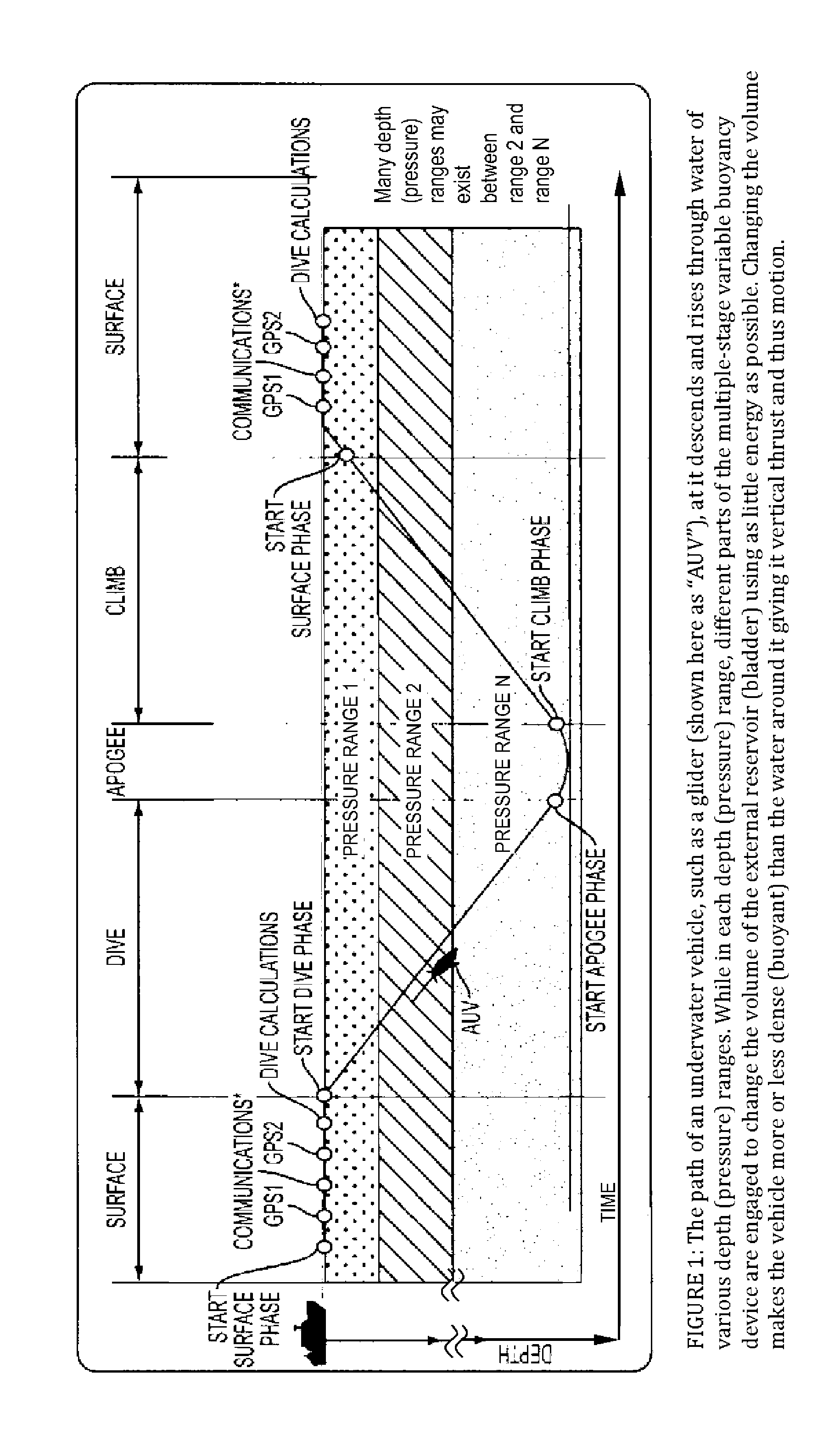
[0017]Reference will now be made in detail to embodiments of the present teachings, examples of which are illustrated in the accompanying drawings.

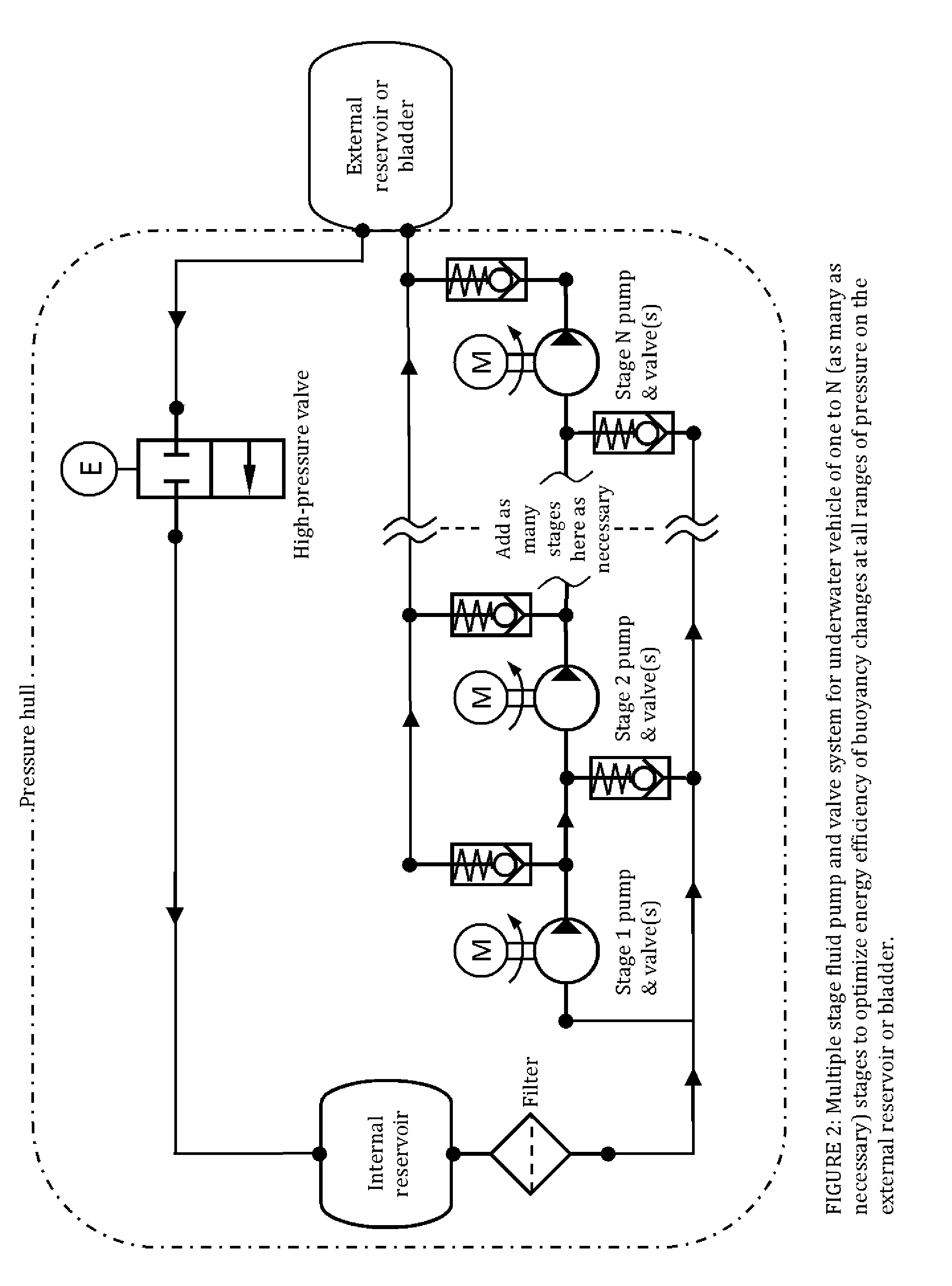
[0018]In many autonomous underwater vehicles, most of the vehicle's energy is used to change buoyancy by pumping fluid of low compressibility into an external reservoir from an internal reservoir. The amount of pressure required to pump fluid into the external reservoir varies with external ambient pressure, which is approximately linearly related to depth. For example, in shallow water the required pressure can have a magnitude of a few hundred pounds per square inch (psi), whereas in deeper water it can have a magnitude of several thousand psi.

[0019]The difference in pressures required to pump fluid into the vehicle's external reservoir creates a design dilemma, because pump and motor combinations that are powerful enough to pump fluid at high pressure for deeper water are not energy efficient for pumping at lower pressures needed in sh...


PUM


Abstract

A multiple stage buoyancy changing system, or variable buoyancy device, for an underwater vehicle. The multiple stage buoyancy changing system comprises: a pressure hull containing a flexibly-sized internal fluid reservoir; a flexibly-sized external fluid reservoir attached to the pressure hull and connected to the internal reservoir; a system of devices and channels configured to move fluid between the internal fluid reservoir and the external fluid reservoir to change a displaced volume of the vehicle. Each stage of the variable buoyancy device can be optimized for maximum energy efficiency while changing the vehicle's displaced volume within an ambient pressure range. A control system for the variable buoyancy device engages different stages depending on ambient external pressure such that maximum energy efficiency is achieved over a large range of pressures/depths.

Description

INTRODUCTION [0001]This application claims priority to U.S. Provisional Patent Application Ser. No. 61 / 309,420, filed Mar. 1, 2010, titled Underwater Glider, and is a continuation of U.S. patent application Ser. No. 12 / 890,584, filed Sep. 24, 2010, titled Autonomous Underwater Vehicle, the disclosures of which are incorporated herein by reference in their entireties.[0002]The present teachings relate to a multiple stage buoyancy changing system for underwater vehicles.BACKGROUND[0003]Underwater vehicles that are propelled by changes in buoyancy have become commercial in recent years and have demonstrated the ability to operate at sea for long periods. Such vehicles, including underwater gliders, are in use, and continue to be developed, for oceanic research, coastline monitoring, and other applications. Existing designs for a buoyancy changing system, or “buoyancy engine,” are typically specialized to perform energy efficiently in limited ranges of depths, or pressures, such as, for...

Claims


Application Information

Patent Timeline
Patent Type & Authority Applications(United States)
IPC IPC(8): B63G8/14B63G8/22
CPCB63G8/001B63G8/08B63G2008/004B63G8/22B63G8/24B63G8/18B63G2008/002
Inventor HUDSON, EDISON THURMANHUGHES, ROBERT EUGENESTAHR, FREDERICK ROLANDGOBAT, JASON ISAACOSSE, TIMOTHY JAMES
Owner IROBOT CORP
Why Eureka
Try Eureka