Device and method for particle beam delivery

a particle beam and device technology, applied in the field of particle beam delivery devices, can solve the problems of “cold” and “hot” dose areas, feasibility or accuracy, and take into account the effect of “hot” dose areas

Active Publication Date: 2011-12-08
ION BEAM APPL
View PDF12 Cites 33 Cited by
  • Summary
  • Abstract
  • Description
  • Claims
  • Application Information

AI Technical Summary

Benefits of technology

[0017]It is an object of the present invention to provide a particle therapy system and method wherein the number of layer paintings (Nlayer_painting) can be more freely chosen,

Problems solved by technology

As discussed by Phillips et al., the use of scanned beams for irradiating a target can, due to organ motion, result in “cold” and “hot” dose areas.
However, Phillips et al. and Bortfeld et al. do not provide any information on what range of values should be selected for Nlayer_painting and they do not take into account the influence of a particular value of Nlayer_painting on the feasibility or accuracy of the delivery of the partial doses by a real particle therapy system.
In particular, the particle therapy system will not be able to deliver partial spot doses which are smaller than the minimum spot dose (Dmin) or it will not be able to deliver them with sufficient accuracy.
This problem becomes even more relevant in case the distribution of the prescribed total spot doses is non-homogenous, i.e. when some spots of the target h

Method used


Image

  • Device and method for particle beam delivery
  • Device and method for particle beam delivery
  • Device and method for particle beam delivery

Examples


Embodiment Construction

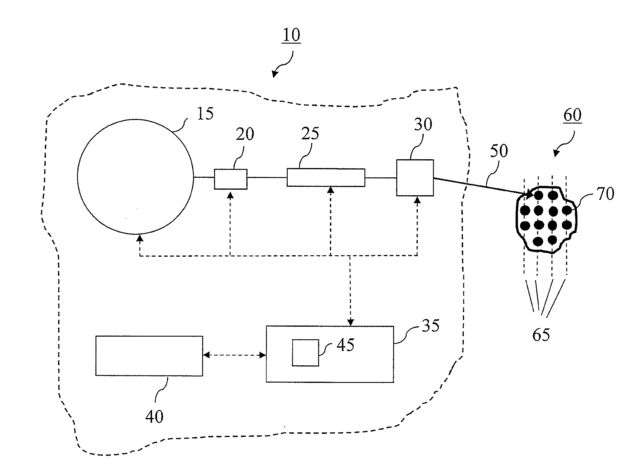
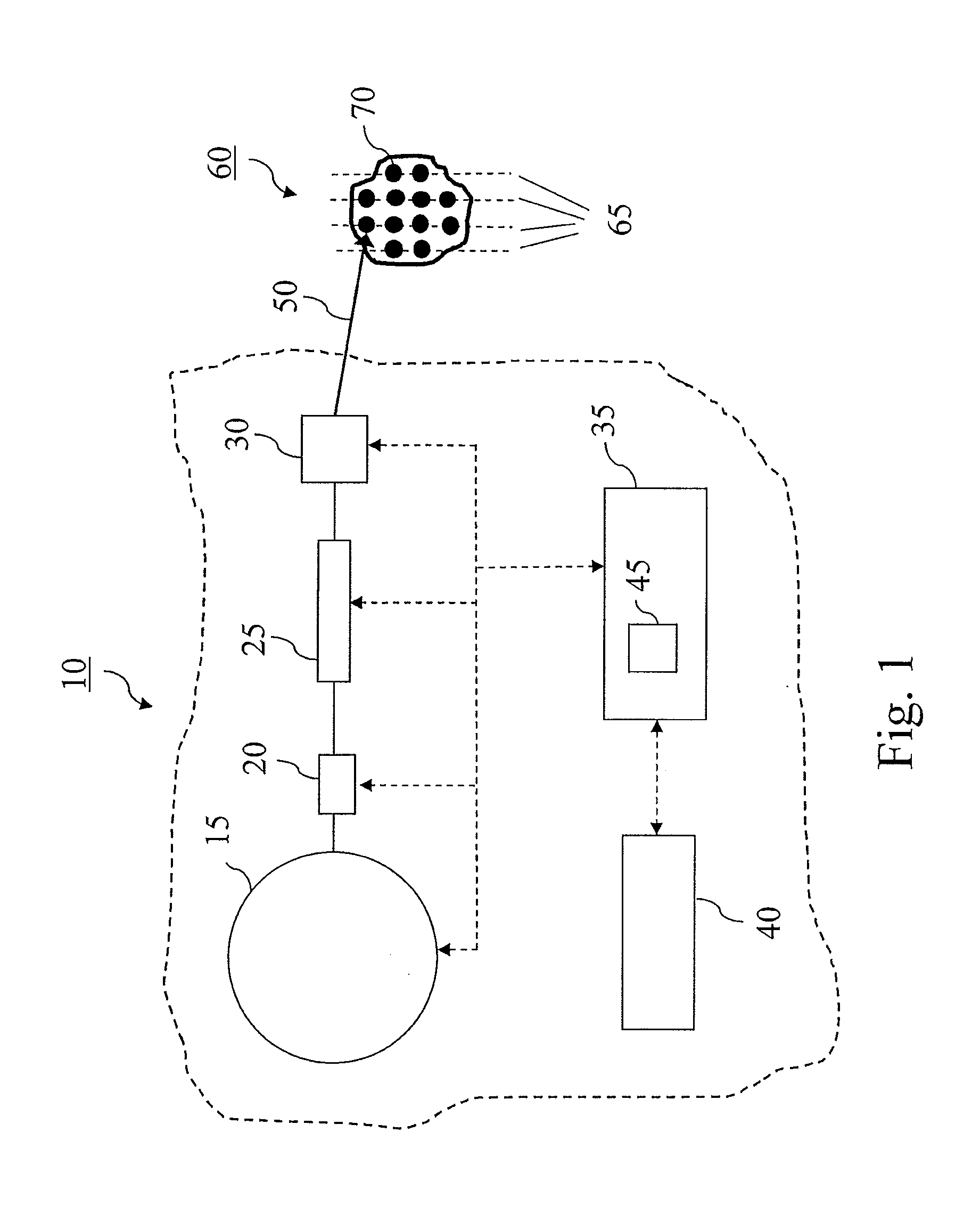
[0042]FIG. 1 shows a schematic representation of an exemplary particle therapy system (10) comprising an accelerator (15) for producing an energetic charged particle beam, an energy selection system (20) to vary the energy of the beam, a beam transport system (25) to transport the beam to a treatment room and a scanning nozzle (30) for scanning the beam (50) over a target (60). The particle therapy system further comprises a control system (35) for controlling the various components of the apparatus such as the accelerator, the energy selection system, the beam transport system, the scanning nozzle, and possibly other components or subcomponents of the apparatus.

[0043]The therapy system furthermore comprises a treatment planning system (40) which interfaces with the control system (35). The treatment planning system creates a treatment plan comprising treatment planning information, i.e. input parameters for performing a target irradiation.

[0044]For the further discussion and exampl...


PUM


Abstract

The present invention relates to a particle therapy system that comprises a spot scanning system to irradiate with a particle beam a plurality of spots in a layer of a target with prescribed spot doses for each spot of the layer. The therapy system is further adapted to perform multiple paintings of the layer and to deliver partial spot doses to selected spots of the layer during each painting time so that each spot of the layer will have received its prescribed dose after completion of the multiple paintings. The therapy system further comprises means for setting the partial spot doses and the number of times that a spot will be selected for irradiation in the course of the multiple paintings to such values that any spot of the layer will never have to be irradiated with a partial dose which would fall below a minimum dose deliverable by the system, and this whatever the number chosen for the number of layer paintings.
The invention also relates to a corresponding irradiation method.

Description

CROSS-REFERENCE TO RELATED APPLICATION[0001]This application claims the benefit of U.S. Provisional Patent Application No. 61 / 352,008, filed Jun. 7, 2010.BACKGROUND OF THE INVENTION[0002]1. Field of the Invention[0003]The present invention relates to a particle therapy system designed for radiotherapy.[0004]More particularly, the present invention concerns a particle therapy system for irradiating with a particle beam a plurality of spots in a layer of a target, said system comprising means for scanning the particle beam over said layer a prescribed number of layer scanning times (Nlayer_painting), and for irradiating selected spots of said layer with partial spot doses (Dspot_partial) in the course of each said layer scanning time so that each spot respectively receives a prescribed total spot dose (Dspot) after completion of the prescribed number of layer scanning times, said system being only able to irradiate a spot with a spot dose which is larger than or equal to a minimum spo...

Claims


Application Information

Patent Timeline
IPC IPC(8): A61N5/10
CPCA61N5/10A61N2005/1087A61N5/1044A61N5/103
Inventor CLAEREBOUDT, YVESCLOSSET, MICHEL
Owner ION BEAM APPL
Why Eureka
Try Eureka