Modulation apparatus, phase setting method and test apparatus

a technology of modulation apparatus and phase setting method, which is applied in the direction of phase-modulated carrier system, modulation, digital transmission, etc., can solve the problems of increasing hardware distortion in the output signal due to hardware, increasing the error of the phase set for the two iq modulators, and increasing hardware distortion of the output signal

Inactive Publication Date: 2011-12-08
ADVANTEST CORP
View PDF3 Cites 25 Cited by
  • Summary
  • Abstract
  • Description
  • Claims
  • Application Information

AI Technical Summary

Benefits of technology

[0013]Therefore, it is an object of an aspect of the innovations herein to provide a modulation apparatus, a phase setting method, and a test apparatus, which are capable of overcoming the above drawbacks accompanying the related art. The above and other objects can be achieved by combinations described in the independent claims. According to a first aspect related to the innovations herein, provided is a modulation apparatus that outputs an output signal having a designated amplitude and a designated phase. The modulation apparatus comprises a first modulating section that outputs a first modulated signal having a predetermined fixed amplitude and a set phase; a second modulating section that outputs a second modulated signal having the fixed amplitude and a set phase; an adding section that outputs th...

Problems solved by technology

However, if the frequency bands of the modulated signals output from the IQ modulators are wide, the distortion of the output signal is increased by the hardware.
However, the frequency band widens if the phases of the two modulated signals are not set appropriately, and this increases the distortion in the out...

Method used


Image

  • Modulation apparatus, phase setting method and test apparatus
  • Modulation apparatus, phase setting method and test apparatus
  • Modulation apparatus, phase setting method and test apparatus

Examples


Embodiment Construction

[0027]Hereinafter, some embodiments of the present invention will be described. The embodiments do not limit the invention according to the claims, and all the combinations of the features described in the embodiments are not necessarily essential to means provided by aspects of the invention.

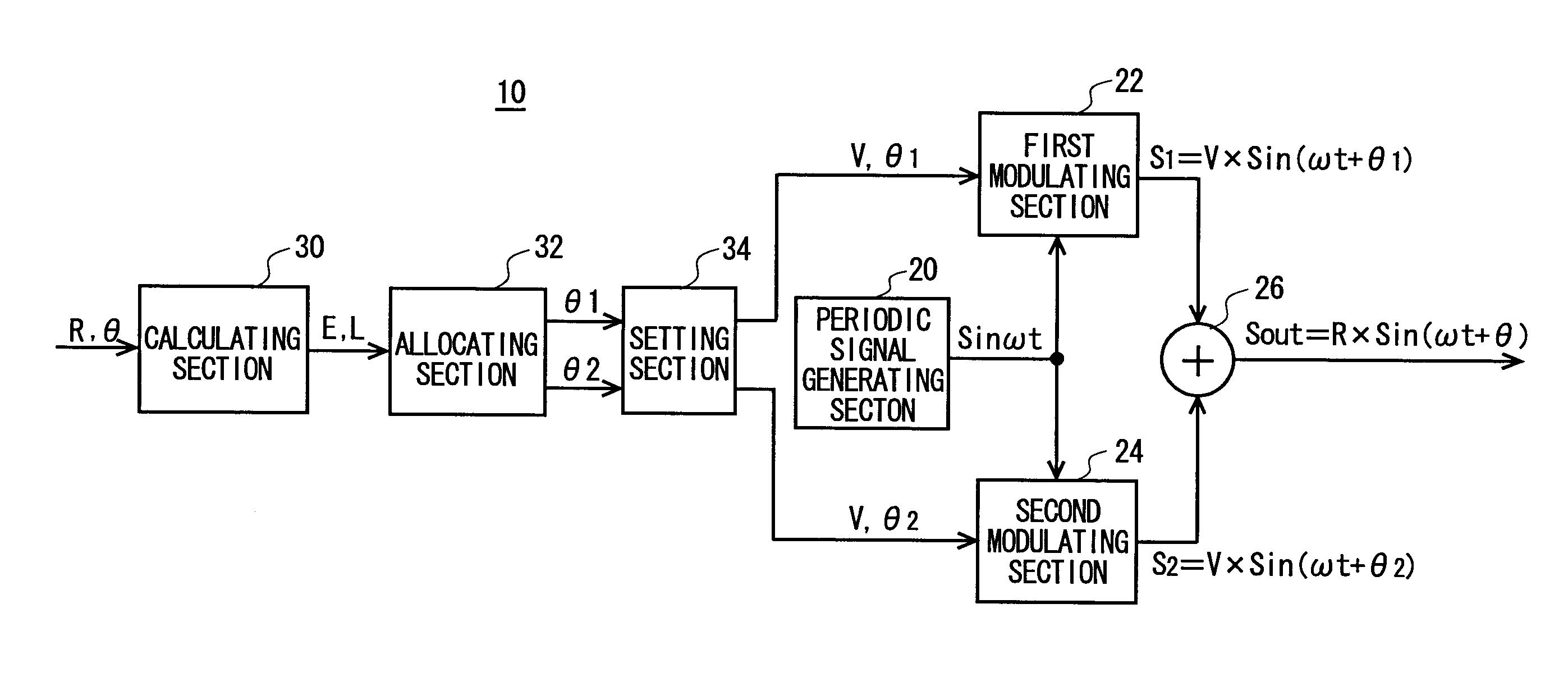
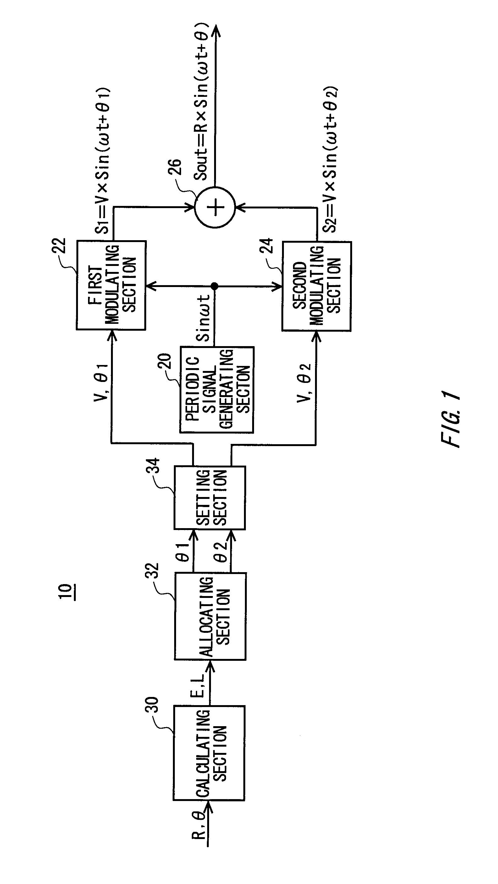
[0028]FIG. 1 shows a configuration of a modulation apparatus 10 according to an embodiment of the present invention. The modulation apparatus 10 outputs an output signal (Sout) with a prescribed frequency and a designated amplitude (R) and designated phase (θ) designated from the outside. The modulation apparatus 10 is an example of a so-called LINC (linear amplification using non-linear components) circuit.

[0029]The modulation apparatus 10 includes a periodic signal generating section 20, a first modulating section 22, a second modulating section 24, an adding section 26, a calculating section 30, an allocating section 32, and a setting section 34. The periodic signal generating section 20 gen...


PUM


Abstract

A modulation apparatus comprising a first modulating section that outputs a first modulated signal having a fixed amplitude and a set phase; a second modulating section that outputs a second modulated signal having the fixed amplitude and a set phase; an adding section that outputs the output signal as the sum of the first and second modulated signals; a calculating section that calculates two phases to be set respectively in the first and second modulating sections, based on designated amplitude and phase; an allocating section that allocates, for the first and second modulated signals, the two phases calculated by the calculating section such that the first and second modulated signals are each connected more smoothly; and a setting section that sets the phase allocated for the first modulated signal in the first modulating section and sets the phase allocated for the second modulated signal in the second modulating section.

Description

BACKGROUND[0001]1. Technical Field[0002]The present invention relates to a modulation apparatus, a phase setting method, and a test apparatus.[0003]2. Related Art[0004]A conventional LINC circuit is known that outputs a modulated signal, as shown in Non-Patent Documents 1 to 5, for example. The LINC circuit uses two IQ modulators to generate two modulated signals with different phases and fixed amplitudes, and outputs the desired amplitude and phase signals by adding together the two modulated signals generated by the two IQ modulators. This type of LINC circuit can output a signal with a high amplitude and low distortion, regardless of the linearity of the amplifier at the output stage.[0005]Non-Patent Document 1: Lars Sundström, “Spectral Sensitivity of LINC Transmitters to Quadrature Modulator Misalignments”, IEEE TRANSACTIONS ON VEHICULAR TECHNOLOGY, VOL. 49, NO. 4, JULY 2000[0006]Non-Patent Document 2: Fernando J. Casadevall, and Antonio Valdovinos, “Performance Analysis of QAM...

Claims


Application Information

Patent Timeline
IPC IPC(8): H03C5/00
CPCH04L27/362H04L27/3488
Inventor KOBAYASHI, NORIO
Owner ADVANTEST CORP
Why Eureka
Try Eureka