
Operation terminal, electronic unit, and electronic unit system

a technology of electronic units and terminals, applied in the field of operation terminals, electronic units, and electronic unit systems, can solve the problems of automatic or unintentional remote operation of electronic units, user discomfort, and change of posture, and achieve the effect of reducing the difficulty of remote operation when the user is not conscious

Active Publication Date: 2011-12-08
SATURN LICENSING LLC
View PDF11 Cites 41 Cited by
  • Summary
  • Abstract
  • Description
  • Claims
  • Application Information

AI Technical Summary

Benefits of technology

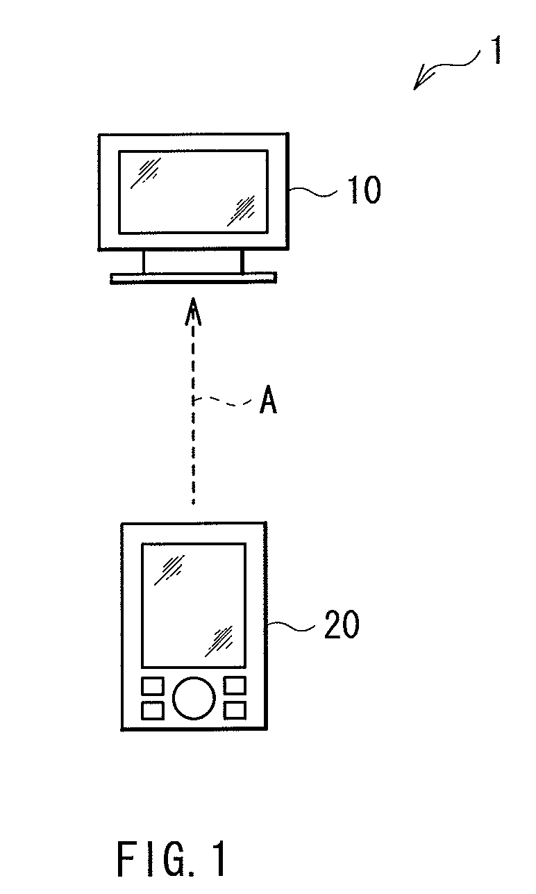
[0004]In remote controls for electronic units, the number of buttons disposed thereon is increasing due to the high functionality and the multi functionality of electronic units of the recent years. Therefore, the user has to look for a button for an operation from many buttons disposed on the remote control, which is troublesome for the user. In view of this, if the above-mentioned sensor such as the gravity sensor and the acceleration sensor is incorporated in a remote control so that the operation can be carried out by changing the posture of the remote control, the number of buttons can be reduced and a remote operation of the electronic unit can be intuitively carried out, which is very convenient for the user.
[0006]It is desirable to provide an operation terminal, an electronic unit, and an electronic unit system, which can reduce a possibility that, when a remote operation of the electronic unit is carried out such as by an orientation and a movement of the operation terminal, an operation is carried out when a user is not conscious.
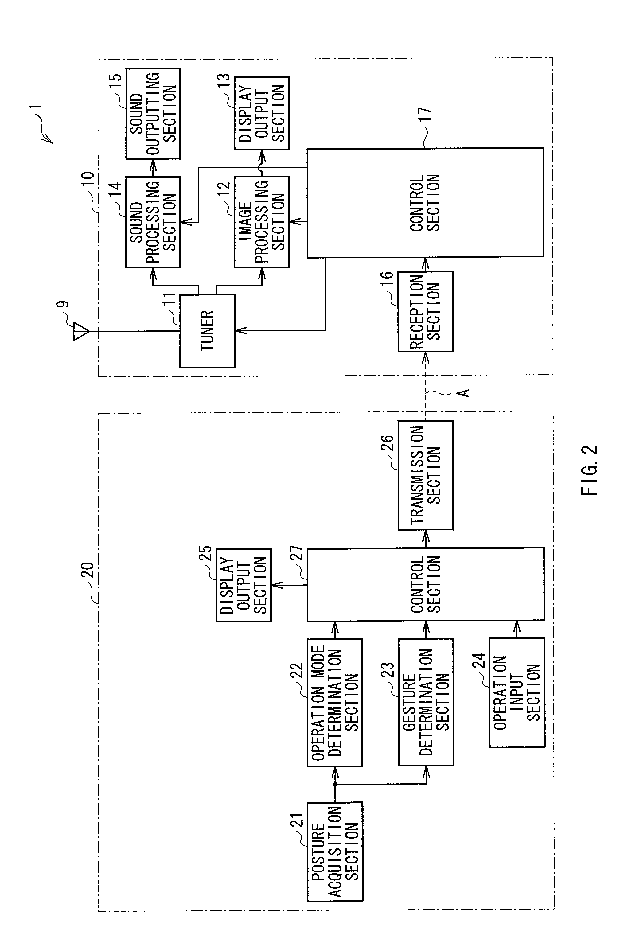
[0020]According to the operation terminal, the electronic unit, and the electronic unit system of the embodiments of the present disclosure, the operation mode is switched to the gesture mode on the basis of the detection result of the posture detection section and then the electronic unit is remotely operated. Therefore, the possibility that the remote operation of the electronic unit is carried out when the user is not conscious can be reduced.

Problems solved by technology

Therefore, the user has to look for a button for an operation from many buttons disposed on the remote control, which is troublesome for the user.
However, in the case where an input operation is carried out by utilizing the sensor incorporated in the remote control, unlike a case where the user operates the electronic unit by consciously pressing the button, there is a fear that the change of the posture is detected even when the user is not conscious and that the remote operation of the electronic unit is automatically or unintentionally carried out.

Method used


Image

  • Operation terminal, electronic unit, and electronic unit system
  • Operation terminal, electronic unit, and electronic unit system
  • Operation terminal, electronic unit, and electronic unit system

Examples


application example

(Application Example)

[0076]FIGS. 8A and 8B illustrate application examples of the gesture motion. FIG. 8A illustrates an operation using up, down, left and right motions, and FIG. 8B illustrates an operation by a free cursor.

[0077]In the electronic unit system 1, by moving the mobile device 20 up, down, left, and right as illustrated in FIG. 8A, the remote operation of the display device 10 can be carried out. Thereby, the electronic program guide (EPG) displayed on the display device 10 can be operated, for example. It is to be noted that the gesture motion is not limited to the operation accompanied by the display on the display device 10. For example, a channel of the display device 10 may be changed by a horizontal movement, and the sound volume may be changed by a vertical movement. Further, the direction of the gesture motion is not limited to the up, down, left and right, and a diagonal movement may be included, for example.

[0078]In addition, in the electronic unit system 1, ...

modification example 1-1

[0082]In the above-mentioned embodiment, the switching of the operation mode is carried out when the change of the posture of the mobile device 20 is detected. However, this is not restrictive. An example is described below.

[0083]FIG. 9 is a flow chart illustrating a case where the switching of the operation mode is carried out according to a present modification example. Operations in steps S11 to S13 and step S15 are the same as those in steps S1 to S3 and step S4 according to the above-mentioned first embodiment (FIG. 7), respectively. That is, the flow chart of the present modification example is a flow chart in which step S14 is added to the flow illustrated in FIG. 7. Below, step S14 is described.

[0084]In step S14, the mobile device 20 checks whether the posture of the mobile device 20 is unchanged (is the same) for more than a predetermined time period. More specifically, the operation mode determination section 22 checks, by using determination results of previous operation ...

modification example 1-2

[0086]In the above-mentioned embodiment, in the gesture mode G, the mobile device 20 remotely operates only the display device 10. However, this is not restrictive. Alternatively, two devices, the display device 10 and a recording and reproducing device 70, may be remotely operated by the mobile device 20 as illustrated in FIG. 10. In this case, the two devices may be operated in the gesture mode G such that, for example, a fast-forward and a rewind of the recording and reproducing device 70 are carried out by moving the mobile device 20 left and right, and that an adjustment of a sound volume of the display device 10 is carried out by moving the mobile device 20 up and down.


PUM


Abstract

An operation terminal includes: a posture detection section detecting a posture of the operation terminal, a change of the posture, or both thereof; a mode selection section selecting, based on a detection result of the posture detection section, an operation mode from a plurality of operation modes including a gesture mode and a non-gesture mode; and a transmission section sending a control command corresponding to the detection result of the posture detection section to an electronic unit when the gesture mode is currently selected.

Description

BACKGROUND OF THE INVENTION[0001]The present disclosure relates to an operation terminal, an electronic unit operated by the operation terminal, and an electronic unit system including the operation terminal and the electronic unit.[0002]In recent years, attention has been paid to electronic units which incorporate a sensor such as a gravity sensor and an acceleration sensor, and can carry out an operation on the basis of information obtained from the sensor. The electronic units equipped with the sensor can be intuitively operated by varying its posture, for example. Therefore, with the increasing high functionality, multi functionality, and complicated user operation of recent electronic units, its utilization is expanding.[0003]For example, Japanese Unexamined Patent Application Publication No. 2002-73247 discloses a portable information terminal which incorporates a tilt detection sensor. When the portable information terminal is tilted, the tilt detection sensor detects its til...

Claims


Application Information

Patent Timeline
IPC IPC(8): G09G5/00G06F3/033G06F3/0346G06F3/038H04M1/72415
CPCG06F3/0346G06F2203/0384H04M1/72533H04N2005/4432H04N21/42222H04N21/42224H04M2250/12G06F3/038G08C2201/32G08C17/02G08C2201/93H04N21/42206H04M1/72415G08C2201/92
Inventor ITO, SHINYAMADA, EIJUOHASHI, YOSHINORI
Owner SATURN LICENSING LLC
Learn More